NTP Server using Raspberry Pi and GPS Module
Gavin Andrews has discovered a fascinating way to use our Com Pi or Serial Pi board with a GPS module to turn the Raspberry Pi into a highly accurate Network Time Protocol (NTP) server.
Why not just use a pool server
Most machines take their time from an internet pool server, and for everyday purposes that is perfectly adequate. The limit is the network path: NTP estimates the offset by measuring the round trip, and any asymmetry between the outbound and return legs shows up directly as error. A few milliseconds is typical, and it moves around with load.
A GPS receiver sidesteps the network entirely. The satellites carry atomic clocks and the receiver solves for time as part of solving for position, so a locked receiver gives you UTC referenced to the same source everyone else is ultimately referenced to. What matters is not the receiver's serial output but its pulse-per-second line: a 1 Hz square wave whose rising edge marks the start of the second to well under a microsecond. The serial data tells the Pi which second it is; the PPS edge tells it exactly when that second began.
The receiver
Gavin's VP Oncore dates from around 1997 and lives in a metal enclosure he built himself, with a MAX232 converting the module's 5 V TTL signals to RS232 levels, a regulator, and an LED on the PPS line. The module speaks a proprietary Motorola binary protocol at 9600 baud, and the PPS output is presented on the DB9 as DCD, a convention from that era. The backup battery had long since given up, so the receiver needed a cold-start command before it would reacquire almanac and ephemeris data and bring the PPS signal back to life.
Getting the signals into the Pi
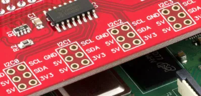
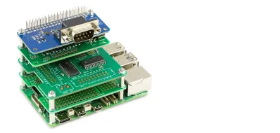
The Pi's UART is available on the GPIO header at 3.3 V, so something has to sit between it and an RS232 device. Gavin found our board and decided it was better value than building his own. He chose the version with the 1 Wire interface as well as the serial port, on the grounds that he might want temperature logging later.
That solved the serial data, but not the PPS. The board handles RX and TX and leaves DCD alone. Looking at the board, Gavin noticed that the MAX3232 has four transceivers and only two of them were in use. So he took DCD from the GPS receiver to an unused input pin on the chip, took the resulting 3.3 V logic signal off the corresponding output pin, and patched it across to GPIO 18. Two wires, and the PPS signal was on the header.
He then put a scope on it to confirm what he had. The pulse is inverted on the wire and inverted back by the MAX3232, and runs roughly 200 ms on, 800 ms off, which is why the LED on the receiver box flashes in a friendly sort of way rather than blinking sharply.
Kernel support
The whole point of PPS is low latency between the edge arriving and the kernel timestamping it, so polling from userspace defeats the exercise. In 2013 that meant running a custom kernel with PPS support compiled in and bound to GPIO 18, and Gavin used a prebuilt image rather than recompiling. He also had to disable gpsd, which the image started automatically and which grabbed /dev/ttyAMA0 out from under him.
With pps-tools installed, ppstest /dev/pps0 showed assertions arriving at exactly one second intervals, with the fractional part sitting a few hundred nanoseconds either side of zero. At that point the hardware work is done and it becomes a matter of pointing ntpd at the right refclock drivers.
For a detailed walkthrough of the setup process and further insights, be sure to visit Gavin’s blog at AardvarkLabs. There, you will find comprehensive guides and additional tips to help you replicate this project.
Read more at his blog at aardvarklabs