
Advantage over default Pi Support
The 1 Wire Pi Plus and 1 Wire Pi Zero are a 1 Wire interface for the Raspberry Pi
12/11/2020
Posted by:
Slawek
![]()
In our marina I've build simple weather station based on RPi Zero. On every fifteen minutes the station is posting on twitter current weather conditions and water level with water temperature. The water level sensor was build as a set of thirty reed switch and resistor network in cooper pipe. Around the pipe there is 3D printed floating buoy with strong neodymium magnets. The voltage from sensor is measured with using the smart DS2438 chip. It also provide measurement of water temperature as well.
The sensor is connected to the RPi zero with 15m cable (1-Wire).
Whole system was working perfectly for one month then sensor died.
I'm not sure, but I suppose, that culprit was the quite violent storm with lot of lightening.
Now I installed the 1 Wire Pi Zero card and new sensor with similar ESD protection on the DS2438 end (DS9503 on OW, resistor-transil on power line, suppressing capacitors).
Before I'll put the sensor into the water I have some questions:
What are advantagee of using 1 Wire Pi Zero module instead of default RPi 1-Wire build-in solution?
Can I expect that my new version of sensor can survive longer than previous?
Do you have some recommendation how to protect 1-Wire sensors in such harsh environment - I mean ESD, inducted spikes etc...?
Sorry for so long post ;-)
Best regards
Slawek
13/11/2020
Posted by:
andrew
![]()
Hello Slawek
The main advantage the 1 Wire Pi Zero has over the default RPi GPIO based 1-wire bus is that the 1 Wire Pi Zero uses a 5V 1-wire bus while the RPi-based network will be running at 3.3V. A higher voltage gives better performance on long 1-wire networks. Maxim has a good tutorial on designing reliable 1-wire networks, you can find it at AN148
The other main benefits of the 1 Wire Pi Zero are the built-in ESD protection using a DS9503 protection diode and the ability to stack up to 4 boards on the Raspberry Pi while only using the two I2C pins, reducing the number of GPIO pins needed.
The DS9503 protection diode on the 1 Wire Pi Zero should give you more protection against EM spikes compared to connecting the 1-wire network directly to the Raspberry Pi GPIO pins. The DS9503 won't help if lightning strikes directly or close to the 1-wire cable but it should reduce the risk of damage from currents induced on the cable by nearby strikes.
A screened cable will help reduce the effects of lightning. You only want to ground the cable screen at the Raspberry Pi end of the cable. It is not generally recommended to ground screened cables at both ends as this can increase the risk of damage from lightning as a nearby strike can cause a voltage difference in the ground at each end of the cable which will induce a voltage on the inner cores.
Do you get many big waves or choppy water in your marina? If you have a row of reed switches in a pipe with loops of wire running down the inside and a strong neodymium magnet on the outside that moves up and down you have basically created a generator. If the float is moved up and down rapidly in rough weather that could induce voltage spikes on the sensor wires. You may want to add Zener diodes across the wires before they connect to the DS2438 to reduce the chance of damage from spikes caused by the magnets.
14/11/2020
Posted by:
Slawek
![]()
Hi Andrew,
many thanks for quick answer and wide explanation.
I don't expect that are many electronics who can survive direct strike of lightning :-( We had in our marina yacht who was hit directly into mast on the bay and EVERY electrical ans electronic devices on board was totally burn out including cables, batteries, engine alternator.....
So I'm fighting only against inductive currents.
Very interesting observation according to moving magnet. Hope that will be not a problem in my case. The sensor is installed under pier between stilts where water is relatively calm.
Here are in Poland on Baltic we have no tides at all, but when there is strong wind coming from the sea we have backflow of water and the level is increasing some times very high. So the my sensor is to alarm the marina stuff and yacht owners on that situation.
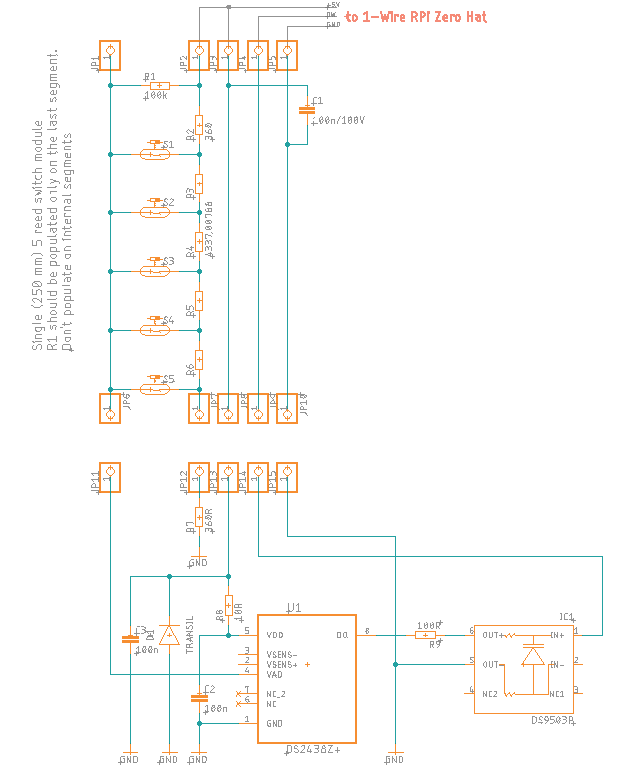
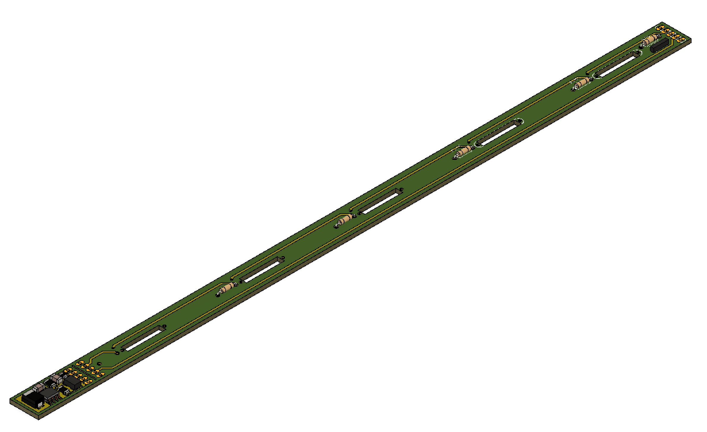
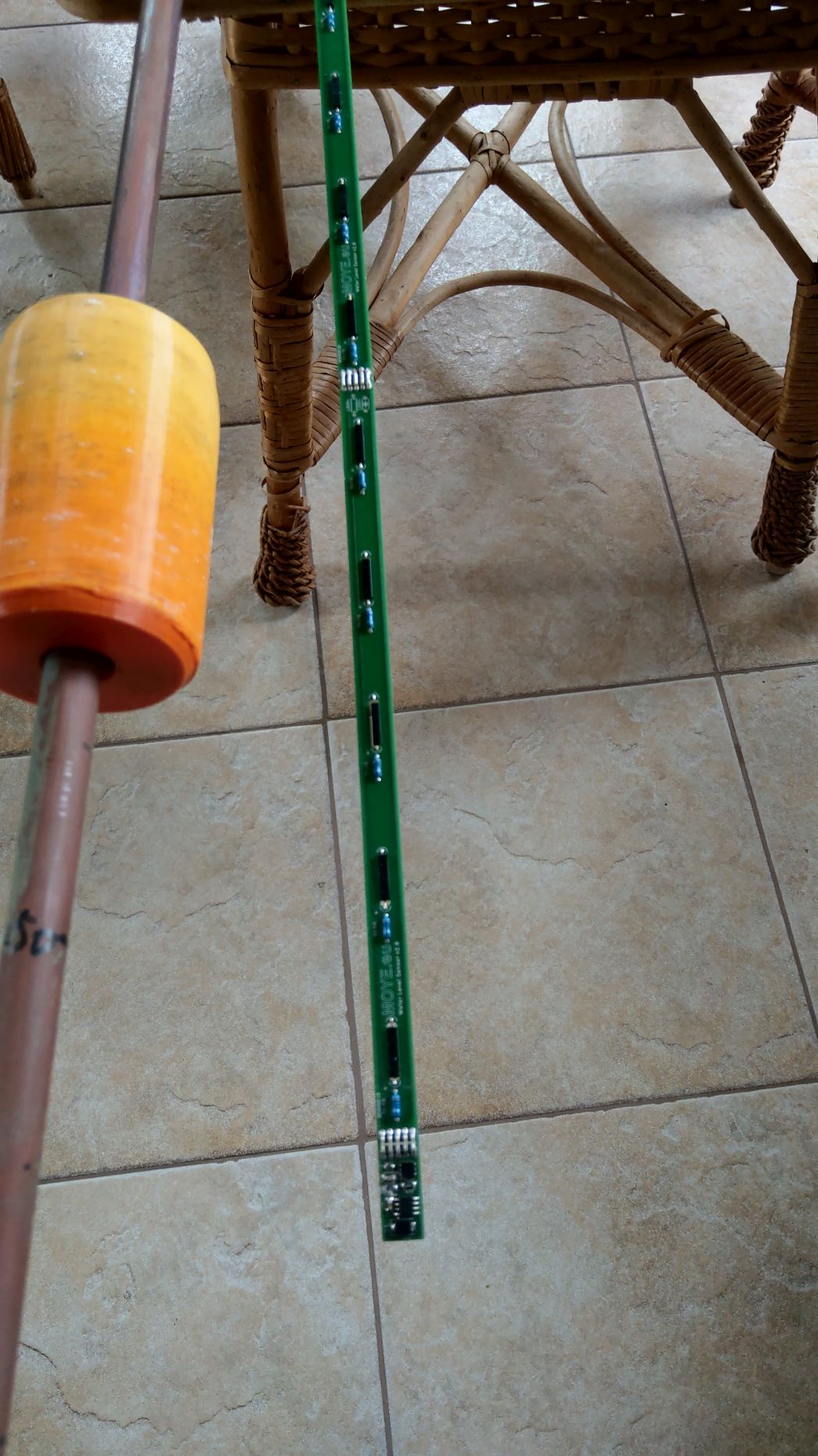
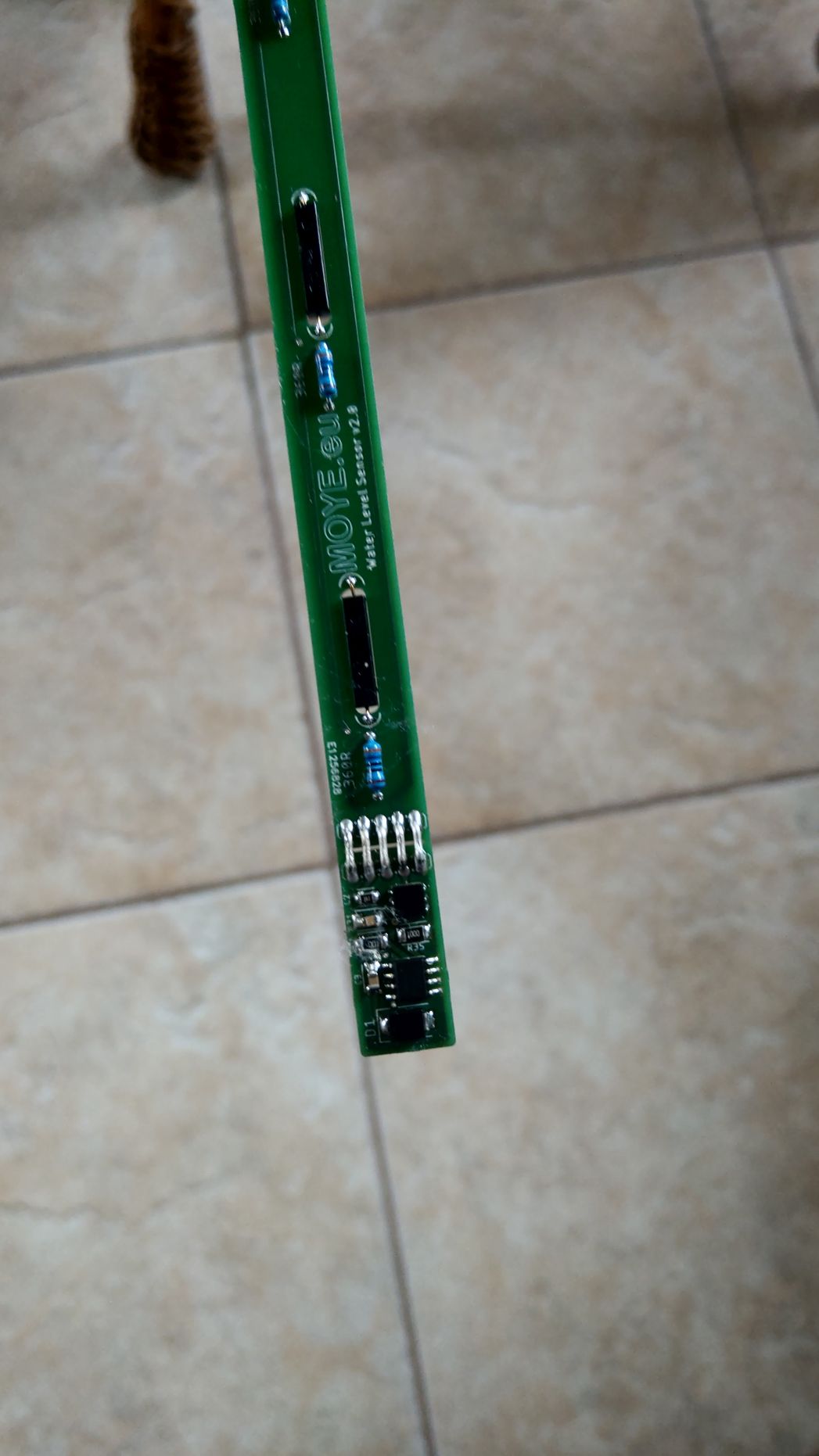
Also in my design I have no loops inside the pipe - I designed a kind of modular PCB for having reed switches distributed evenly. There are only switches without coil of course. One module is 250mm long with 5 switches and I have 6 modules 1,5m long sensor. At the end of module there is small snapp-off PCB with the DS2438 and surrounding components.
I will install the sensor next week and we will see.
Here you have some pictures to show schematic and my idea of design.
many thanks for quick answer and wide explanation.
I don't expect that are many electronics who can survive direct strike of lightning :-( We had in our marina yacht who was hit directly into mast on the bay and EVERY electrical ans electronic devices on board was totally burn out including cables, batteries, engine alternator.....
So I'm fighting only against inductive currents.
Very interesting observation according to moving magnet. Hope that will be not a problem in my case. The sensor is installed under pier between stilts where water is relatively calm.
Here are in Poland on Baltic we have no tides at all, but when there is strong wind coming from the sea we have backflow of water and the level is increasing some times very high. So the my sensor is to alarm the marina stuff and yacht owners on that situation.
Also in my design I have no loops inside the pipe - I designed a kind of modular PCB for having reed switches distributed evenly. There are only switches without coil of course. One module is 250mm long with 5 switches and I have 6 modules 1,5m long sensor. At the end of module there is small snapp-off PCB with the DS2438 and surrounding components.
I will install the sensor next week and we will see.
Here you have some pictures to show schematic and my idea of design.
Note: documents in Portable Document Format (PDF) require Adobe Acrobat Reader 5.0 or higher to view.
Download Adobe Acrobat Reader or other PDF reading software for your computer or mobile device.