KKSB case for Raspberry Pi 5 Tall Dual Hat Review
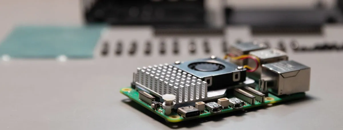
At AB Electronics UK we are always looking for new cases that will work with our range of Raspberry Pi development boards. One case that recently came to our attention was the KKSB case for Raspberry Pi 5 Tall Dual Hat. This is a metal case from Swedish company KKSB for the Raspberry Pi 5, designed to hold the Pi and two Hats or other development boards.
We bought this case ourselves at full retail price from The Pi Hut. KKSB did not supply a sample, did not contact us, and has had no involvement in or sight of this review before publication.
First Impressions
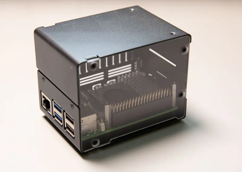
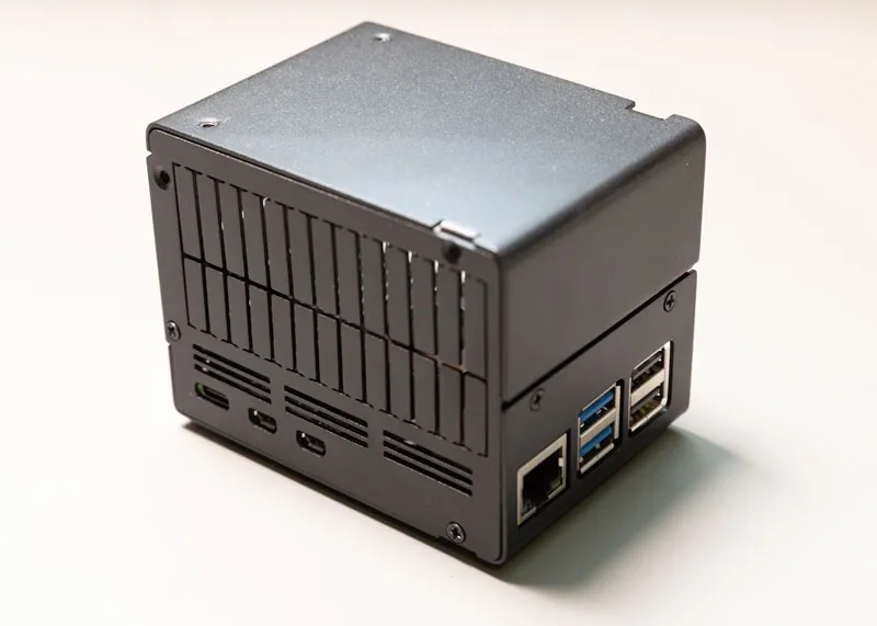
The case arrived in a small cardboard box. Our first impression upon opening the box and inspecting the contents was that the case was well designed and sturdy. The case is built using three powder coated metal panels and a clear acrylic sheet. The metal panels make up the three sides where the connectors sit on the Raspberry Pi as well as the top. The acrylic sheet covers the back face behind the GPIO connector and allows you to see inside the case. All of the panels screw together with small cross screws.
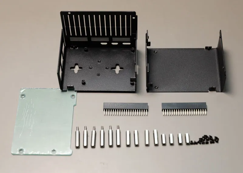
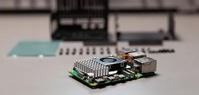
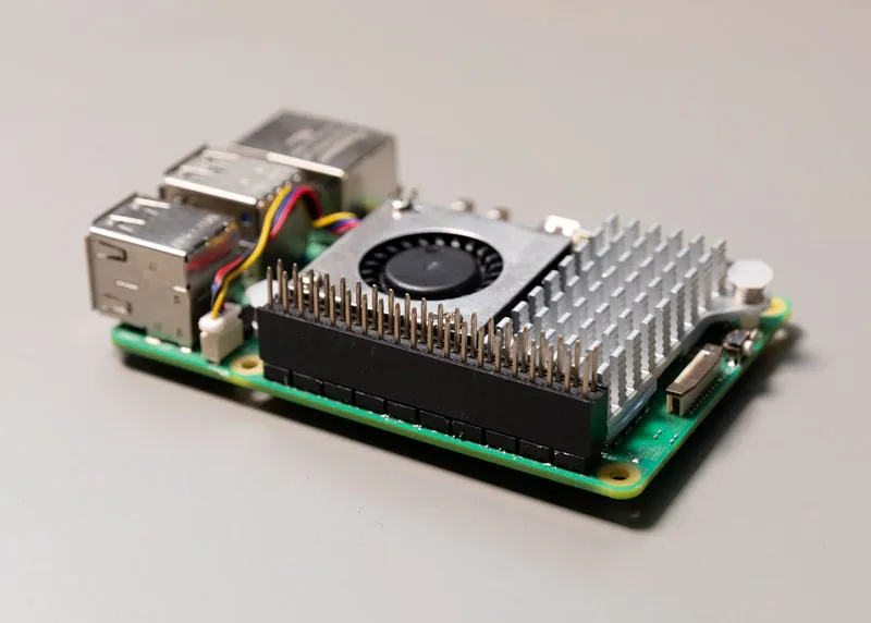
The case comes with a range of mounting posts, bolts and two 40 pin headers. The headers extend the height of the GPIO header if you are using the fan cooler on the Raspberry Pi. The Raspberry Pi 5 runs hot when out in the open so we would recommend using the fan if you want to run it inside a case. The case includes ventilation holes on one side to allow airflow for the fan.
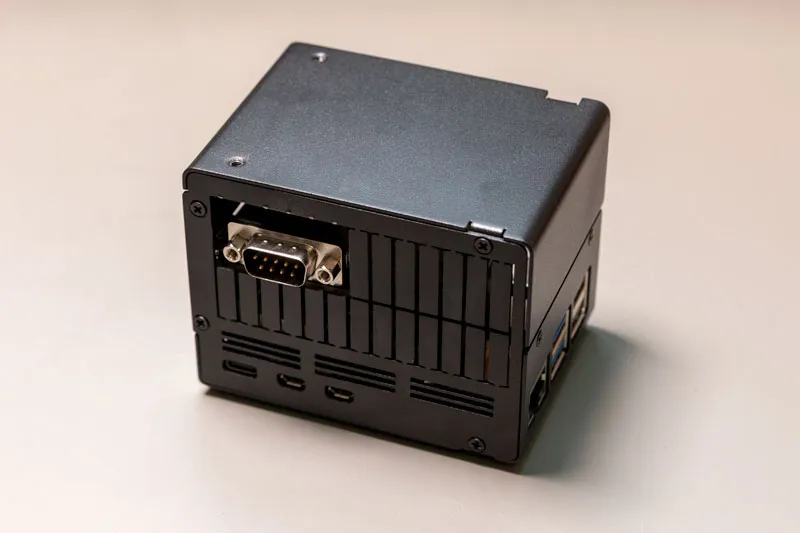
The top half of the case side where you connect power and HDMI includes two rows of metal fingers that can be folded out and removed. This allows you to run cables inside the case to connect wires to any hats or development boards. It can also provide exit holes for connectors, like those found on our Serial Pi Plus or 1 Wire Pi Plus.
Assembly
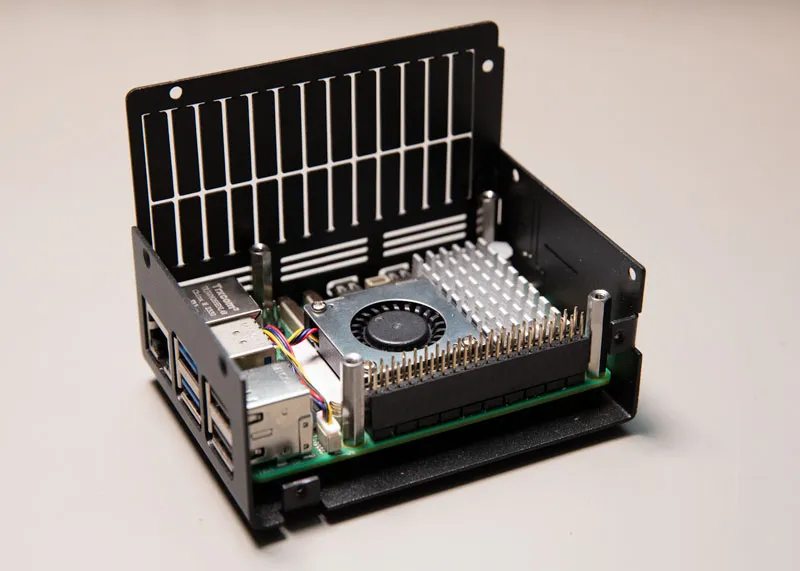
The first step in assembling the case was to fit one of the 40 pin headers on the Raspberry Pi GPIO header. The Raspberry Pi was fitted into position and we used four of the supplied 20mm mounting posts to hold the Raspberry Pi down inside the case. Two of the posts are quite tight against the end of the case so a 5mm nut spinner will make the job of tightening them easier. The next step was to fit the sides and the top onto the case. A small cross head screwdriver is needed to screw the case together.
Testing with our Development Boards
With the case assembled the next step was to test how well it works with our development boards. All of our boards should be compatible with the case but for this test we chose four boards, the IO Pi Plus, Expander Pi, ADC Pi and Serial Pi Plus.
The first board to fit was the IO Pi Plus. The supplied 20mm mounting posts and connector extend the height of the GPIO header to give plenty of clearance above the cooling fan. The IO Pi Plus sits just above the bottom of the removable fingers on the HDMI and power side of the case so this would allow easy access for cabling to the board.
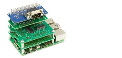
KKSB calls it a dual hat case but with the IO Pi Plus fitted there was still plenty of space above the board and we found that you could stack three of our development boards inside the case.
We used our mounting kits to hold the boards apart. The supplied mounting posts use M2.5 threads which are the same size as our mounting kits so we were able to screw our mounting posts into the supplied posts creating a very sturdy build.
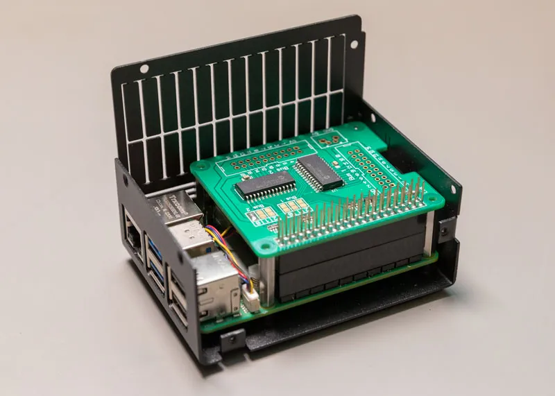
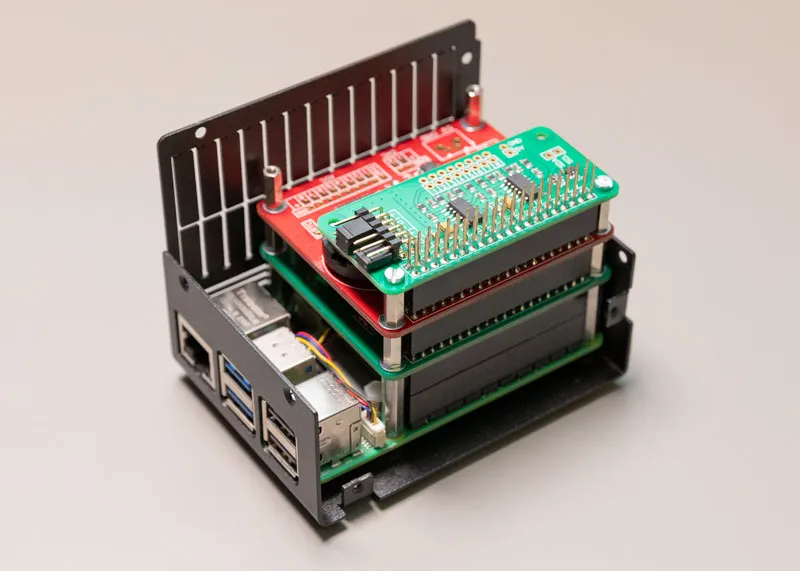
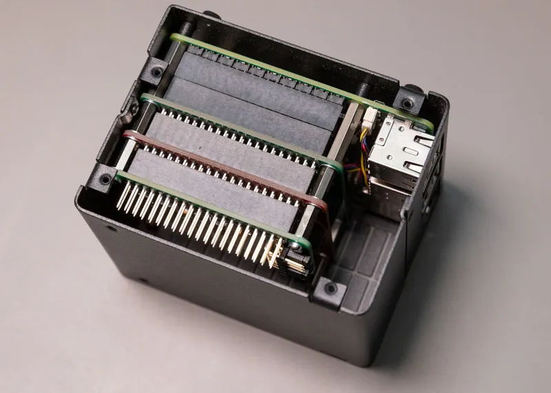
The three boards we fitted into the case were the IO Pi Plus, the Expander Pi and the ADC Pi. These three boards combined would give you 48 GPIO pins, 16 ADC inputs, 2 DAC outputs and a battery backed RTC. A lot of digital and analogue IO in a small space.
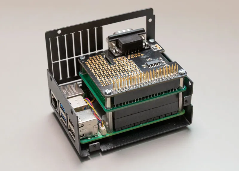
We also tested the case with a Serial Pi Plus stacked on top of the IO Pi Plus. Six of the metal fingers needed to be removed to make room for the DB-9 connector on the Serial Pi Plus.
Thermal Testing
A case is useless if the Raspberry Pi inside overheats so our next step was to test the thermal performance of the case with a Raspberry Pi 5 and our development boards installed.
We ran four tests, the first was with the Raspberry Pi 5 running at idle without any development boards installed.
The second test was the Raspberry Pi 5 with the CPU running at 100% without any development boards installed.
The third test was with the Raspberry Pi 5 running at idle with three development boards installed.
The fourth test was the Raspberry Pi 5 with the CPU running at 100% with three development boards installed.
The development boards we used for the test were the IO Pi Plus, Expander Pi and ADC Pi.
To measure the performance of Raspberry Pi we used the following bash script which logs the temperature, CPU frequency, the throttled status of the CPU, the CPU core voltage, the fan state and the fan speed. The values are saved into a CSV file at 2 second intervals.
#!/bin/bash

FAN_RPM=""
for f in /sys/class/hwmon/hwmon*/fan1_input; do
  [ -r "$f" ] && { FAN_RPM="$f"; break; }
done

COOL=""
for d in /sys/class/thermal/cooling_device*; do
  case "$(cat "$d/type" 2>/dev/null)" in
    *fan*) COOL="$d"; break ;;
  esac
done

MAXSTATE="NA"
[ -n "$COOL" ] && MAXSTATE=$(cat "$COOL/max_state" 2>/dev/null)
echo "# fan rpm:   ${FAN_RPM:-not found}"
echo "# fan state: ${COOL:-not found} (max_state=$MAXSTATE)"

# --- log ---
echo "time_s,temp_c,arm_mhz,throttled,core_v,fan_state,fan_rpm" > thermal.csv
start=$(date +%s)
while true; do
  t=$(( $(date +%s) - start ))
  temp=$(vcgencmd measure_temp | grep -oE '[0-9]+\.[0-9]+')
  clk=$(( $(vcgencmd measure_clock arm | cut -d= -f2) / 1000000 ))
  thr=$(vcgencmd get_throttled | cut -d= -f2)
  v=$(vcgencmd measure_volts core | grep -oE '[0-9]+\.[0-9]+')
  fs="NA"; [ -n "$COOL" ] && fs=$(cat "$COOL/cur_state" 2>/dev/null || echo NA)
  rpm="NA"; [ -n "$FAN_RPM" ] && rpm=$(cat "$FAN_RPM" 2>/dev/null || echo NA)
  echo "$t,$temp,$clk,$thr,$v,$fs,$rpm" | tee -a thermal.csv
  sleep 2
done
The CPU frequency and core voltage vary depending on the processing load. If the CPU temperature reaches 80°C it will begin throttling the performance of the CPU which is logged by the bash script.
The fan state and speed will vary depending on the CPU temperature. The fan is off below 50°C. Above 50°C the fan speed increases with the CPU temperature from 2500rpm at 50°C to 10000rpm at 75°C.
During the idle test the only programs running, other than the default background processes, were the temperature logging script and an SSH shell connection. The Raspberry Pi was connected to a network through the ethernet socket and no monitor or USB devices were connected.
To test the CPU under load we used the program stress-ng with the command stress-ng --cpu 4 --cpu-method matrixprod --timeout 1200s. The program puts a 100% load on the four Cortex-A76 cores in the Raspberry Pi 5.
Each test ran for 20 minutes to give the Raspberry Pi and the case time to reach a stable temperature. After each test the Raspberry Pi was left to cool in an idle state for 30 minutes before running the next test.
The ambient temperature while runnings the tests was 25.8 °C with a humidity of 64%.
Test 1: Raspberry Pi 5 running at idle
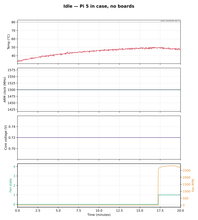
In the first test with the Raspberry Pi running in idle the temperature rose over 17 minutes from 33°C to 50°C. Once it reached 50°C the fan turned on which kept the temperature stable around 50°C. The clock speed and core voltage stayed constant throughout the test.
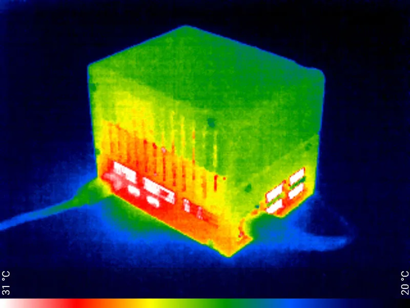
The photo from the thermal camera shows the heat is mostly contained in the bottom of the case around the Raspberry Pi with the hottest points around the vents and connectors.
Test 2: CPU running at 100% without any Hats or development boards installed.
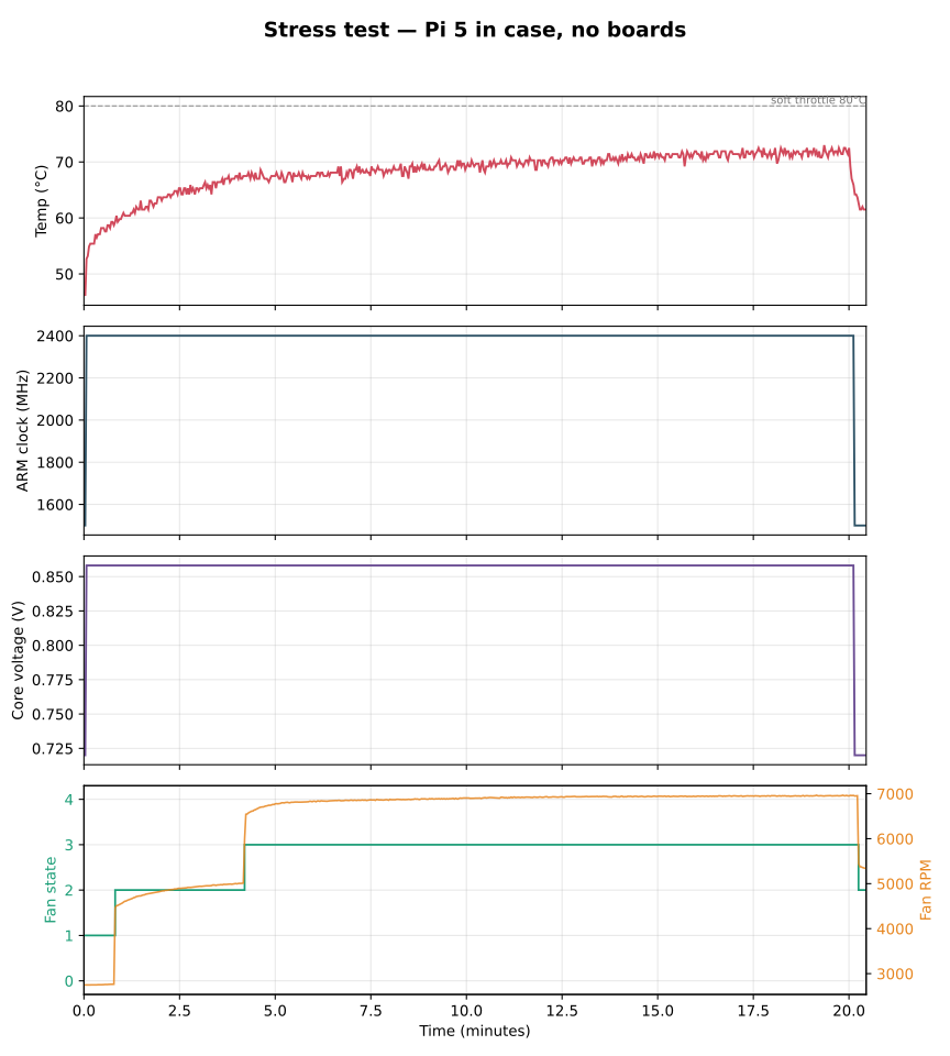
In the second test the temperature rose quickly to 65°C and continued to rise more slowly until the 17 minute mark where it sat at round 72°C. The fan ramped up in speed along with the temperature increase but maxed out at 7000rpm.
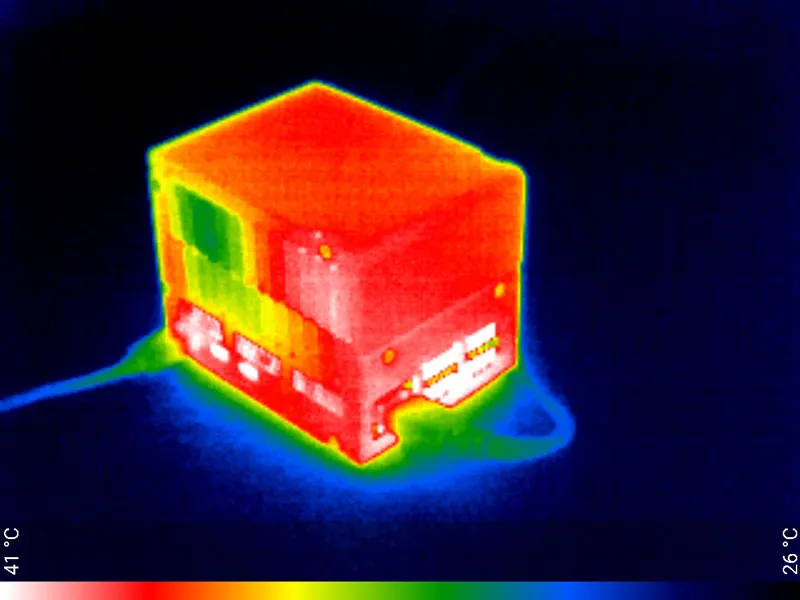
The photo from the thermal camera shows that the temperature throughout the case is more even, sitting at around 38°C. As with the first test the ports and vents are the hottest points showing the fan is working for venting the hot air outside.
Test 3: Raspberry Pi 5 running at idle with three development boards installed
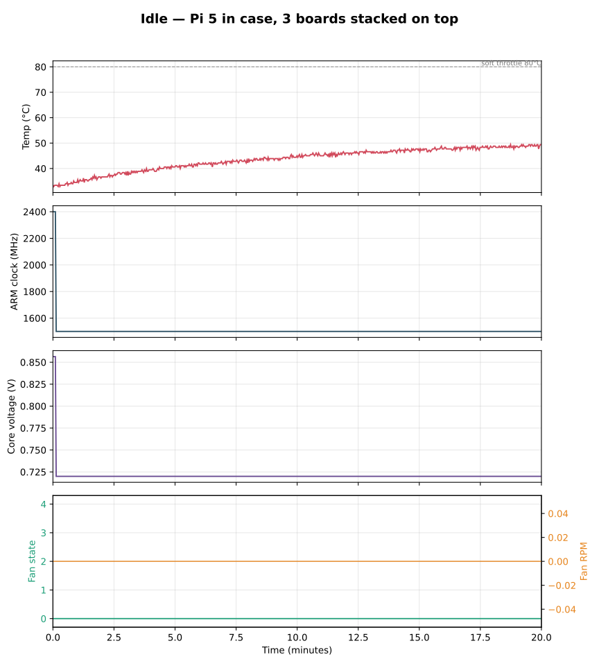
In the third test three development boards were installed and the Raspberry Pi was left at idle. As with the first test the CPU rose in temperature for the first 17 minutes but peaked at 49.4°C, just below the threshold for the fan to start spinning.
We do not know why it ran slightly cooler with the development boards installed. One possible theory is the flat development board sitting above the heatsink caused the warm air to be forced out of the side vents in the case through convection, instead of sitting in the top of the case where the heat could build up.
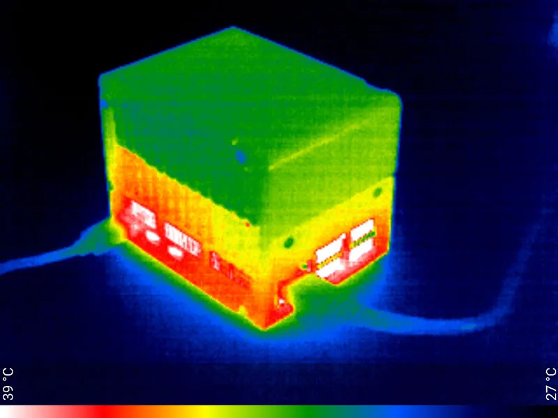
The image from the thermal camera shows a clear difference in temperature above the height of the development boards, indicating that the heat is being transferred out of the case through the vents.
Test 4: Raspberry Pi 5 with the CPU running at 100% with three development boards installed
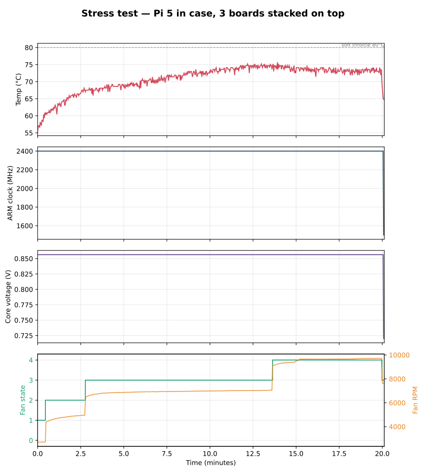
In the fourth test the temperature ramped up faster than the first stress test reaching 75°C in just over 12 minutes. The fan speed increased to 10,000rpm at which point the CPU temperature dropped slightly to 73°C where it remained stable for the rest of the test.
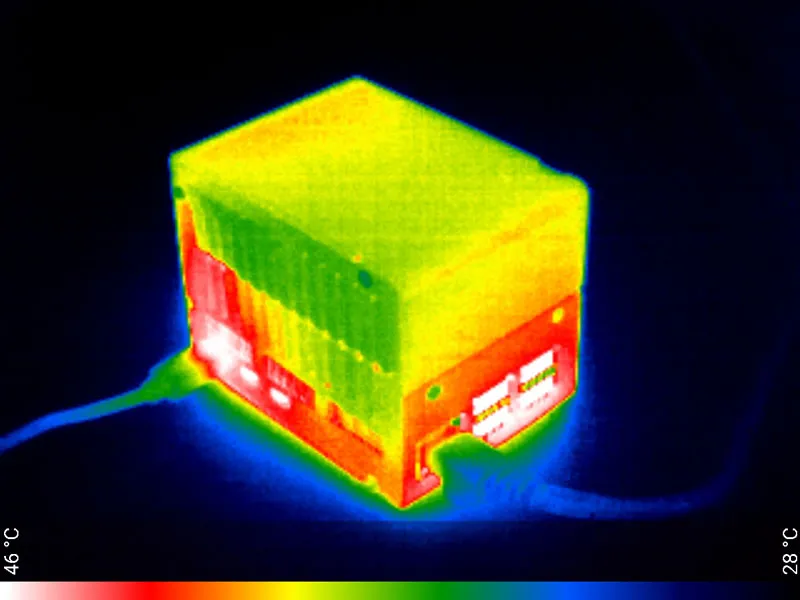
The thermal image shows as before the bulk of the heat is contained below the height of the development boards with the hottest points being around the connectors and power cable. Even with the CPU running at 75°C the case only reached a peak temperature of 46°C showing the fan was venting the majority of the heat out through the side vents.
Final Thoughts
Overall we found this case to be well designed. The metal construction is solid and the clear acrylic on one side allows you to see inside to any status indicators on the hats inside.
Even under full load with a full compliment of development boards the temperature never rose above 76°C so the CPU did not get hot enough to need to throttle down.
The case is held together with 12 screws so if you are constantly swapping hats or development boards it can take a while to disassemble and reassemble but if you are looking for something to hold your Raspberry Pi and development boards in a sturdy metal enclosure this case from KKSB may be the ideal choice.