
Controlling relay board // Relay switches off while turning other pin off
The IO Pi Plus is a 32 channel MCP23017 GPIO expander for the Raspberry Pi
29/10/2018
Posted by:
rriveral
![]()
The issue is, that if I turn a relay on, output pin 1 for example, then if I send a command to turn on relay number two at output pin 2, then the relay at pin 1 shuts off, not sending the command, I believe this might be related to the pull-down resistors of the bus? but the pi already has? so probably adding external PS? thoughts?
Thank you!
30/10/2018
Posted by:
andrew
![]()
When you write to the IO Pi to update a pin are you using the writepin() or writeport() function? writepin() should update one pin without affecting the others but with writeport() it updates all pins on the port so writing to pin 2 without also setting pin 1 would make pin 1 turn off. To set pins 1 and 2 to an on state you would need to write 0x03 or 0b00000011 in binary.
If you are using writepin then there could be a bug in the software in which case if you could let me know which programming language you are using I will check to make sure it is working correctly.
30/10/2018
Posted by:
rriveral
![]()
def main():
"""
Main program function
"""
bus = IOPi(0x21)
bus.set_port_direction(0, 0x00)
bus.write_pin(pin,1) "I parse here the pin that I want to write to"
I dont know if the port direction shall be set everytime that I trigger the outputs? or is stored somewhere?
30/10/2018
Posted by:
andrew
![]()
I have just tested the python library by writing to the pins individually and it is not resetting the previously set pins so I don't think there is a bug with the software library.
Are you powering the relays directly from the IO Pi outputs or through a relay driver like a MOSFET or Darlington transistor? Each output pin can supply a maximum of 25mA and an overall limit of 125mA per chip so one possible reason for it not working is you are drawing too much current from the pins which could cause the IO chip to reset. Also, make sure your relays have reverse protection diodes across the coil inputs otherwise you could get a voltage spike on the input when the relay turns on or off which would also cause problems with the IO chip.
24/04/2022
Posted by:
coolDhana
![]()
Thought to post in same thread.
I have 4 of IOPi plus boards. I also am trying to achieve same thing with few 16 ch relay boards. But I decide to test my programming by connecting LEDs instead of relay boards.
So my setup is, just 01 IOPi plus with few LEDs and a Raspberry Pi with python 3.9
Then I got the same issue as “rriveral” had. Then I tried changing IOPi plus boards and Raspbery pi OS.
I could use “writepin(1,1)” to light LED 1. But when I send next command as “writepin(2,1)” LED 1 is turning off while LED 2 light up. Then I tried send “writepin(1,1)” again. Then LED 2 become off while LED 1 light up. I tried with other pins as well. Some pins are working fine but some don’t.
Eventually I could get good results from all pins with “writeport()” command using binary.
But prefer to use writepin() instead of writeport() because changing selected pin status without affecting others is very hard for me with writeport().
Please update us if this is any issue with library or somewhere.
Thank you
24/04/2022
Posted by:
andrew
![]()
I have just tested the IO Pi python library using the code below to turn pins 1 to 8 on in turn and it appears to be working correctly.
#!/usr/bin/env python
from __future__ import absolute_import, division, print_function, \
unicode_literals
import time
try:
from IOPi import IOPi
except ImportError:
print("Failed to import IOPi from python system path")
print("Importing from parent folder instead")
try:
import sys
sys.path.append("..")
from IOPi import IOPi
except ImportError:
raise ImportError(
"Failed to import library from parent folder")
def main():
iobus = IOPi(0x20, False)
iobus.set_port_direction(0, 0)
iobus.write_port(0, 0)
time.sleep(0.1)
iobus.write_pin(1, 1)
time.sleep(0.1)
iobus.write_pin(2, 1)
time.sleep(0.1)
iobus.write_pin(3, 1)
time.sleep(0.1)
iobus.write_pin(4, 1)
time.sleep(0.1)
iobus.write_pin(5, 1)
time.sleep(0.1)
iobus.write_pin(6, 1)
time.sleep(0.1)
iobus.write_pin(7, 1)
time.sleep(0.1)
iobus.write_pin(8, 1)
time.sleep(0.1)
iobus.write_port(0, 0)
if __name__ == "__main__":
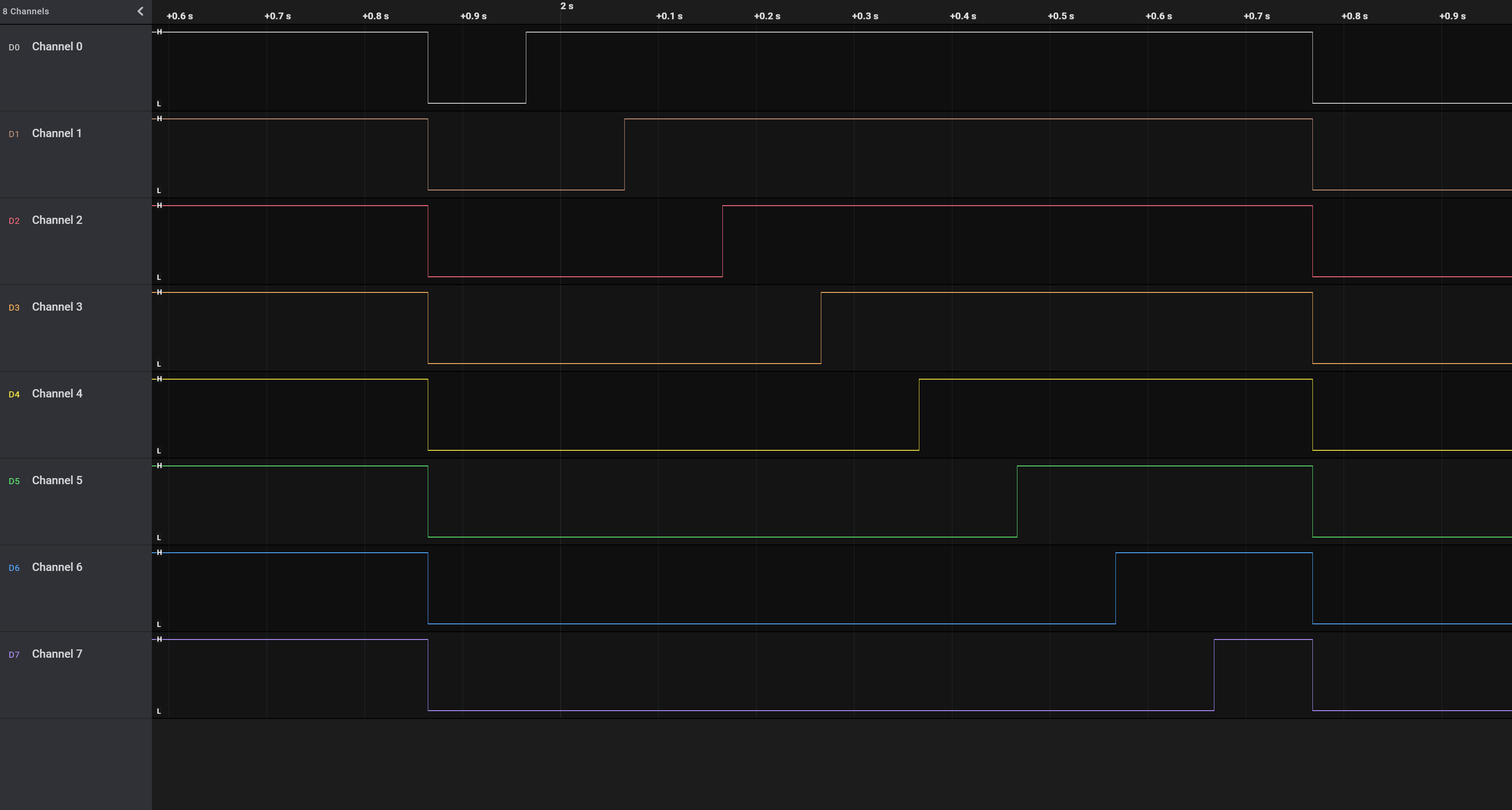
main()The screenshot below from my logic analyser shows each pin turning on in sequence.
Are you using the current version of the IO Pi python library from our GitHub repository?
What value resistor are you using with the LEDs? The IO Pi Plus has a current limit of 25mA per pin and 125mA overall per bus so if the LEDs are drawing too much current that could cause erratic behaviour.
31/07/2022
Posted by:
kemmi
![]()
I’ve been playing with IO Zero 32 along with a 16-relay board. During the tests everything works great - the right relays are turning on and off exactly when I want them to, but… It’s getting weird when I turn on the 230V, so the relay board can do the real job (for example moving the blinds). Now, when I turn on, then off a single relay, I won’t be able to turn it (or any other) on. The only solution at that point is setting the port direction again, so I assume the chip has restarted - but I don’t know why. Also, the set-direction trick doesn’t always work - I’m getting IOError 121 pretty often.
IOZero32 and relay board (5V) are powered by external power supply - I don’t use PI’s pins for this. I’ve tried two different PIs (3 and 4) and two different IO Zero 32.
Do you have any advice on what could be the problem?
01/08/2022
Posted by:
andrew
![]()
Do your 230V cables run close to the cables connected to the IO Zero 32 or the Raspberry Pi power supply cable? If the high voltage cables run close or parallel to the low voltage cables they could induce a voltage spike when the 230V turns on causing a glitch either in the IO Zero 32 or the Raspberry Pi. Try keeping the cables as far apart as possible or use shielded cables between the relay board and the IO Zero 32 with the shield connected to ground.
Another possible cause for the problem is the 230V device is creating a brownout on the power supply when it turns on, making the voltage drop for a few milliseconds which would be enough to cause problems on the IO Zero 32. You could try powering the IO Zero 32 from the Raspberry Pi power supply and the relay board from the external power supply, connecting a common ground between the two power supplies. Adding a large value capacitor of 1000uF or higher across the V+ and GND pins on the IO Zero 32 will also help smooth out the drops or spikes in the voltage going to the board.
Forum Notice – Closure to New Posts
As part of our compliance with the UK’s Online Safety Act, the AB Electronics UK support forum is now closed to new posts and replies.
We understand the importance of continued support for our products, so if you have a technical query or require assistance, please use the Contact Form or consult our Knowledge Base for helpful articles and documentation.
We appreciate your understanding and continued support.
Note: documents in Portable Document Format (PDF) require Adobe Acrobat Reader 5.0 or higher to view.
Download Adobe Acrobat Reader or other PDF reading software for your computer or mobile device.