
Using the IO Pi Plus pins as inputs
The IO Pi Plus is a 32 channel MCP23017 GPIO expander for the Raspberry Pi
08/02/2020
Posted by:
Computerman142
![]()
I am using an IO Pi Plus set as inputs on one bus, and currently running a test setup for what will be a larger project involving sensors, which have a detect/sense out terminal at 5v. The plan would be connect these sense outputs to the IO Pi as 5V inputs on each pin for each sensor. I would like to set it up so that IO PI is reading/polling all 16 pins indviually all the time, and print a message in the terminal window when a 5V input is detected on any of the 16 pins from any sensor. The pins need to be set up indiviually as each pin or set of say 4 pins will control differnt sets of LED's to switch them on or off depending if there is a 5V input or not. I have been trying a bit of code out (below) however not having much look, I have attempted to remove bits and add bits of code that I think may help, however nothing has worked. I have tried applying 5v input to pin 16 on Bus 2 from the senso for testing, however nothing is printed on screen, if I change != 0 to != 1 it constantly says motion detected instead. I have also tried applying the - or ground source from the 5V supply to the GND pin, however that does not work and nothing printed on screen when I apply 5V to pin 16.
#!/usr/bin/env python
from IOPi import IOPi
import time
busin = IOPi(0x24)
busin.set_port_pullups(0, 0xFF)
busin.set_port_pullups(1, 0xFF)
busin.set_port_direction(0, 0xFF)
busin.set_port_direction(1, 0xFF)
busin.invert_port(0, 0xFF)
busin.invert_port(1, 0xFF)
busin.read_port(0)
busin.read_port(1)
while True:
busin.read_pin(16)
if (busin.read_pin(16) != 0):
print("Motion detected.")
Any assistance would be very much appreciated.
Many Thanks
Rhys
09/02/2020
Posted by:
andrew
![]()
If the sensors you are using output 5V then you will need to disable the internal pull-up resistors and set the port inversion to 0 so the inputs show as 1 when they are at 5V.
Depending on the type of sensor you are using you may need to add a 10K pull-down resistor between each input and ground to pull the input to 0V when the sensor is not active. Without a pull-down resistor, the input could be left in a floating state where it will randomly jump between high and low.
The code below should do what you need. I tested it on an IO Pi Plus with a 10K resistor connected between input 16 and ground and when the input is connected to 5V it shows the "Motion detected." message.
#!/usr/bin/env python
from IOPi import IOPi
import time


def main():
    '''
    Main program function
    '''
    busin = IOPi(0x24)

    busin.set_port_pullups(0, 0x00)
    busin.set_port_pullups(1, 0x00)
    busin.set_port_direction(0, 0xFF)
    busin.set_port_direction(1, 0xFF)
    busin.invert_port(0, 0x00)
    busin.invert_port(1, 0x00)

    while 1:
        if (busin.read_pin(16) == 1):
            print("Motion detected.")
        else:
            print("")


if __name__ == "__main__":
    main()
09/02/2020
Posted by:
Computerman142
![]()
Thank you for taking the time to look into this and write some code for me, much appreciated. I have given the code a go, however it works backwordly, so constantly says motion detected, until a 5v input is applied from the sensor in which it stops saying motion detected until the 5v input is taken away. I havent tried the 10K resistor as I dont have any to hand. I do plan to get some, so when I do, just tobe sure do I apply the resistor from the GND pin on the IO Pi, or ground of the 5v supply, to the 5v input on the IO Pi? So basically liked between GND and the pin on the IO Pi. The sensors inputs and output are as follows VDC+ 24V Sensor Power In, VDC- GND/0V Sensor Power In, Earth, Relay common 5V supply into sensor, 5v Relay detect/sense out, 5v No detect / no sense out. So effectively the relay switches between the two outputs on the relay, depending on if there is motion detected. I am connecting the 5V detect/sense out to the IO Pi.
Many Thanks
Rhys
09/02/2020
Posted by:
andrew
![]()
The ground between your Raspberry Pi power supply and the 5V supply should be connected together so you have a single common ground across your power supplies. Connecting the resistor between the input on the IO Pi bus and the IO Pi ground should work.
If you find that the inputs are working backwards then you can either invert the port by changing
busin.invert_port(0, 0x00)
busin.invert_port(1, 0x00)
to
busin.invert_port(0, 0xFF)
busin.invert_port(1, 0xFF)
or change the if statement to
if (busin.read_pin(16) == 0):Either should work.
09/02/2020
Posted by:
Computerman142
![]()
Thanks again for your assistance. The plan is to have the Pi and the 5V supply that runs through the sensor relays to be from the same power supply, so hopefully the ground from the supply will work ok. I have tried changing the code around as suggested, both the if statement and inverting the port, however it has not made any difference and still continously says motion detected until a 5V input is applied.
Many Thanks
Rhys
09/02/2020
Posted by:
andrew
![]()
Have you checked the output from your sensors with a multimeter to make sure they are going high to 5V when activated and not pulling low to ground?
Hopefully, it should start working properly when you connect a pull-down resistor to each input. At the moment without the pull-down the input will be floating so any internal capacitance in the IO chip will cause it to give strange readings.
09/02/2020
Posted by:
Computerman142
![]()
I have checked the output from the sensor, and it puts out 5V when it detects motion and 0V or near enough to 0v, such as a few mili-volts when there is no motion detected.
I did give the code ago without the sensor plugged in, and that also constantly says motion detected too, not sure if that makes a difference. When the sensor is plugged in with no 5V input, the IO Pi knows its there as the motion detected messages flickers as it contantly prints on the terminal window. It does not flicker when the sensor is not plugged in but just constalty prints motion detected. I will give the resistor a go though, I have ordered some so will let you know how that goes.
Many Thanks
Rhys
11/02/2020
Posted by:
Computerman142
![]()
Would the 10K resistor between ground and the input pin also act a current limiter, so that the IO Pi Plus does not draw too much current from the 5V supply, that is connected through the sensor to it? Reason I ask is the IO PI Plus is fried now, it was working fine and then suddenly I can smell a burning smell coming from the IO Pi and the chip is very hot, after this it no longer works, it just randomly does it, one bus went when I applied power to raspberry Pi, IO Pi Plus and sensors, and the other bus it just randomly happened while sat there saying motion detected when there wasnt. Do you have recommendations for current and voltage protection of inputs into the IO Pi to protect it from this?
Thanks
Rhys
11/02/2020
Posted by:
andrew
![]()
A 10K resistor between ground and the IO Pi input should just increase the current draw from your sensor by 0.5mA. The idea behind using a pull-down resistor is when the voltage from the sensor drops to 0V any voltage on the input wire left over from capacitance in the wire and IO input will flow through the resistor to ground pulling the voltage down to 0V.
It would not limit the current going to the input pin, which is done internally in the IO chip and when the pin is set as an input it should only draw around 1µA, well below the 125mA the chip is designed to handle.
The most common cause for the IO chip getting hot is too much current being drawn from the pins when they are set as outputs. Each output channel can source up to 20mA but it normally takes more than that for the chip to warm up. As you have set the IO bus as inputs it shouldn't be drawing anywhere near enough power to get warm.
Another possibility is the voltage on the input is too high. The maximum voltage for the input is 5.5V so if the voltage on an input is above that it could make the chip get hot and stop working correctly. When you measured the voltage on the sensor did you measure between the output and the ground on the sensor or the ground on the Raspberry Pi? A ground loop problem where the grounds are not all connected together properly could cause a potential difference between different parts of the circuit so while the voltage between the sensor output and the sensor ground would be 5V the voltage between the sensor output and the Raspberry Pi ground could be a different value.
I had an issue once where I used two switch-mode power supplies and did not connect the grounds together correctly. The result was accidentally pushing 125V into the GPIO header on a Raspberry Pi which luckily only killed the UART pins.
The third possibility is a fault with the chip on the IO Pi Plus. As a faulty board could explain the problems you are having I will send you a replacement tomorrow so we can rule that out as the issue. Do you want me to send it to the same address as your previous order?
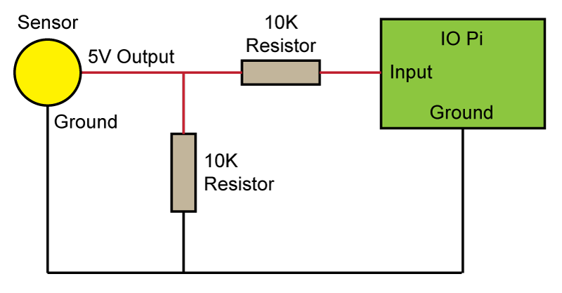
When the new board arrives it may be worth adding an extra 10K resistor on each input as shown in the diagram below. This will limit the current that can flow into or out of the IO Pi reducing the risk of damaging the board. Also before you connect your sensor to the IO Pi try testing it first by connecting the inputs to the 5V pin on the Raspberry Pi GPIO header via a 10K resistor. That will allow you to make sure the IO Pi is working correctly and narrow the problem down to the sensor output.
12/02/2020
Posted by:
Computerman142
![]()
Thank you for your explanation, makes more sense to me now, to know how the resistor would interact with the IO Pi and how the IO Pi deals with input current limiting etc.
I wondered similar to that in that the IO Pi maybe outputting 5V especially in the case when it was switched on. What is the IO Pi's main default starting state, so soon as power is applied, are the pins outputting 5V or does it literally do nothing until code is run to control the function of the pins?
When I checked the output voltage from the sensor, it was around 4.95V, I was measuring between the 5v output from the sensor and the ground on the power supply that also runs the 5v supply through the relay in the sensor, that then goes out the sensor and connects to the IO PI Plus as an input. I will check the grounds later, I think may need to review that.
I had wondered if maybe the chips on the board were faulty as it randomly occured, we can try rule the board out. Yes if you could send it to my address on the previous order, that would be great, many thanks. Do you need any order confirmations or anything?
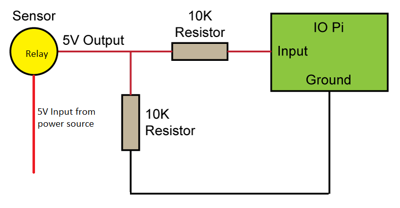
The sensor itself doesn't have a ground for the 5V side, the connections to the sensors are 24V DC IN, Earth, Relay Common(5V input from power source), Relay Sensor Sense/Detect Out(5v to IO PI Plus as an input), Relay Sensor No Sense/No Detect Out(5V Out, this terminal is for when no motion is detected, not currently wired to anything) The 5V input to the sensor relay common terminal and then out to the IO Pi comes from the switch mode power supply. The circuit is 5V loop in through the relay in the sensor and then out to the IO Pi, the ground from the 5V supply isn't used with the sensor. I can still wire it as you have drawn up however the ground between the resitsor and sensor on the left side is not present. I have attached a modified version of your diagram, would this work ok with those two 10K resistors wired like that, without a ground to the sensor?
If you need me to take any photos of the pins outs of the sensors and or setup, etc, please let me know.
Many thanks
Rhys
12/02/2020
Posted by:
andrew
![]()
I have posted a new IO Pi Plus to you so hopefully, you should receive it in a day or two.
When the IO Pi is switched on it defaults to all of the bus pins set as inputs with internal pull-ups disabled.
You will need some sort of ground connection between the sensor and the IO Pi or Raspberry Pi otherwise there is no return path for the current flowing into the IO Pi input.
Could you post a photo of the sensor you are using and your setup as well as a part number for the sensor?
12/02/2020
Posted by:
Computerman142
![]()
Thank you, much appreciated, I will let you when it has arrived.
Ah ok so that should be ok, could of this been a factor however that may of caused it to burn out at power up?
Not sure how I would do that as it doesnt have a ground on the 5V side. Unless there is a way to overcome this, or create one somehow. Hopefully the photos below will give an indication of a possible potential issue.
The sensor I am using it one not normally used with a RPi or IO Pi plus, however the project will involve these type sensors so would like to hoepfully get them working, if possible. The sensor is a pedestrain on crossing radar sensor normally used at pedestrian crossings. It's make and model is AGD220 however you may not find any documentation, so may need to refer to its newer version the AGD226 for details, if you need it.
Sensor/Radar:
Power Supply:
One is a 24V DC (bottom of photo) switch mode power supply to power the sensor/radar itself. The other is a 5V DC (top of photo) switch mode power supply, to power relay boards, soon the RPi itself as well, however isn't currently, and also for the 5V loop through the sensor/sensor relay common and into the IO Pi Plus.
Close up of the cable colours for the sensor/radar. Red: 24V DC +, Black: 24V DC ground, Green: Earth, White: Relay Common - 5V input, Blue: Relay radar motion detect out - 5V to IO Pi Plus, Yellow: Relay radar no motion detect out - not connected yet.
Setup:
This is how it is all laid out now, with the broken IO Pi Plus on the paper. The IO Pi connected directly to the RPi on the GPIO pins is for outputs to control lights.
Let me know if you need any more information, and thanks again so far for your help.
Many Thanks
Rhys
13/02/2020
Posted by:
andrew
![]()
Thanks for the photos, I have a better understanding of what you are doing now.
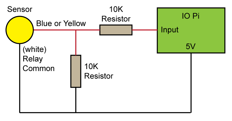
According to the manual for the sensor, it uses an optoisolator for switching the outputs so it may be better to use the 5V output on the IO Pi Plus to connect to the relay common input instead of an external power supply. The current draw from the 5V pin on the IO Pi will be minimal and it should be more reliable that way.
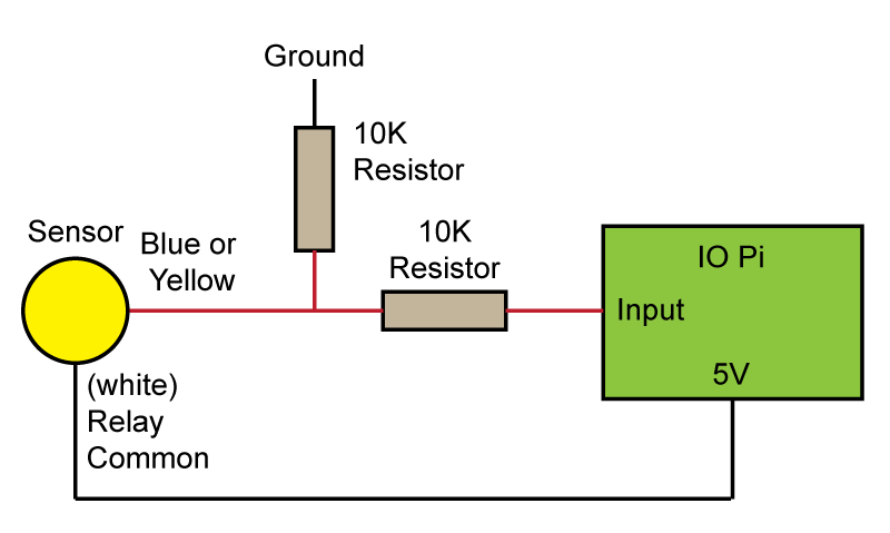
I have made a new wiring diagram below based on the sensor manual wire colour scheme. I'm not sure if the blue or yellow wire is needed, you will have to measure that to see which one goes high when the sensor activates.
13/02/2020
Posted by:
Computerman142
![]()
No worries. I have got the Pi powered from the 5V switch mode supply now in the top of that photo previously, so all grounds in one place.
Oh right maybe the newer type use an opto-isolator I must of not seen that. To be honest I havent opened a newer type, I know mine has a conventional relay though, as I have opened it in the past. I will use the 5V outputs on the IO Pi plus pins, as you suggest when I wired it up.
Thank you for the new updated diagram, I will wire up the sensor, with the 10k resistors, when the IO Pi Plus and resistors arrive, and report back both good or bad. Both blue and yellow are needed in some way. Blue goes high when motion is detected, yellow goes high when no motion is detected. One question I have is will wiring all 16 pins up like in the diagram with 16 sensors (1 for each pin) work ok, if I was to do this? Also the IO PI's working as inputs will be not connected directly on the GPIO pins, like the other IO PI plus you can see in the photo with the RPi. Would it be ok to power the IO Pi's from the same 5V switch mode supply that also powers the Raspberry Pi now, as a external supply, or shall I keep them powered from the main Raspberry Pi header pins?
Many thanks again
Rhys
14/02/2020
Posted by:
andrew
![]()
To connect 16 sensors you will just need to duplicate the circuit above 16 times so each sensor has its own pair of resistors.
If you are using a single 5V power supply then the external IO Pis can be powered through the 5V and ground pins on the IO Pi instead of the GPIO connector. You may want to remove the Link solder jumper on the IO Pi if it is being powered externally, even from the same power supply, otherwise, you will be powering the Raspberry Pi through the GPIO header which will bypass any short circuit protection in the Pi.
You will need to connect the 3.3V from the GPIO header on the Raspberry Pi as this is needed to translate the I2C bus from 5V to 3.3V. A ground wire from the GPIO header may also be needed to reduce noise on the I2C bus.
14/02/2020
Posted by:
Computerman142
![]()
Thank you for your explanation, I will wire them up like you suggested. I have received the IO Pi Plus, many thanks for that, however I have not recieved my 10K resistors I bought yet, so will have to wait until next wait before I get back to you on how the new circuit setup works.
Many Thanks
Rhys
18/02/2020
Posted by:
Computerman142
![]()
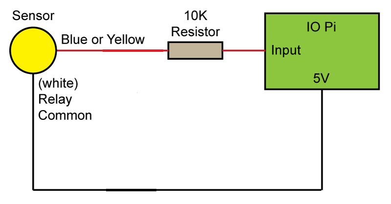
I have been testing out the new IO Pi Plus and resistor circuit, which I wired up as suggested on the last diagram. However when I did this I found this does not work, as it makes both the common and the sense out relay terminals in the sensor live at 5V due to the resistor in the middle carrying the voltage accross to the input side from the 5V side. I confirmed this when I removed the input to the IO PI side from the blue wire on the sensor, and them measured the voltage on the relay terminal wires. How is best to wire it so the voltage goes in through relay common (white wire) and then back out through sense out (blue wire)? Would taking the resistor out like below diagram work ok, or do I need to wire it up slightly differently? Or have both resistors in parrelel one on 5V and one on input?
 Many Thanks
Rhys
19/02/2020
Posted by:
andrew
![]()
Sorry, I made a mistake on the last diagram. The second 10K resistor should have been connected to ground instead of 5V as on the earlier diagram.
Here is a revised version that should work correctly.
19/02/2020
Posted by:
Computerman142
![]()
I have wired it up, and it works great and displays motion detected on screen when the sensor detects motion, and is not opposite in its operation either which is great. Many thanks for your help with this, much appreciated. I am now going to add an 1.9V LED on the input side to notify of when motion is detected, I will wire this between the input side and the ground with a 150 ohm resistor on the input side.
Thanks
Rhys
Note: documents in Portable Document Format (PDF) require Adobe Acrobat Reader 5.0 or higher to view.
Download Adobe Acrobat Reader or other PDF reading software for your computer or mobile device.