
Communication between Rpi and Arduino/ESP32 with RS485 and SN65HVD72
The RS485 Pi is an RS485 interface for the Raspberry Pi
28/06/2021
Posted by:
Herant
![]()
Hi,
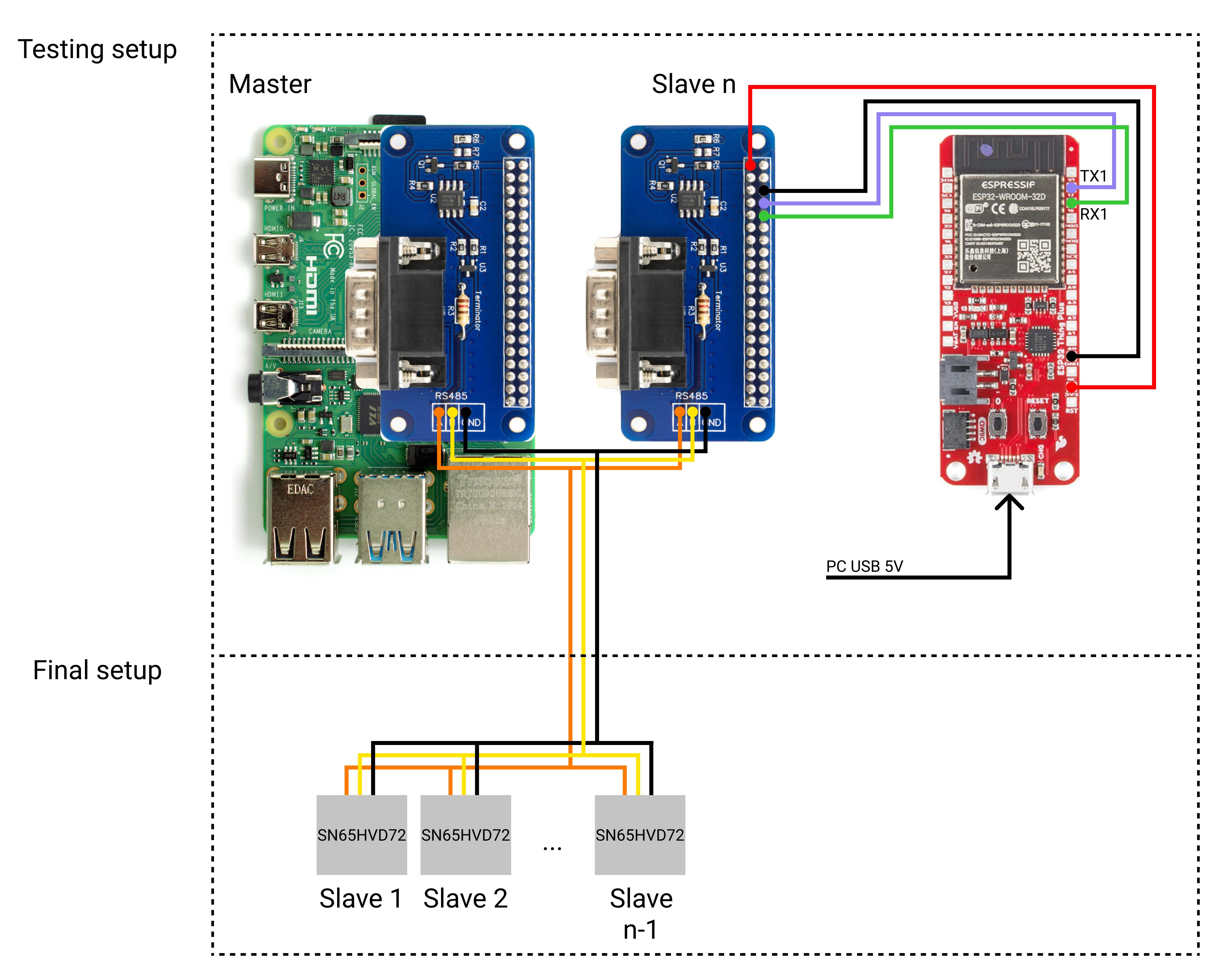
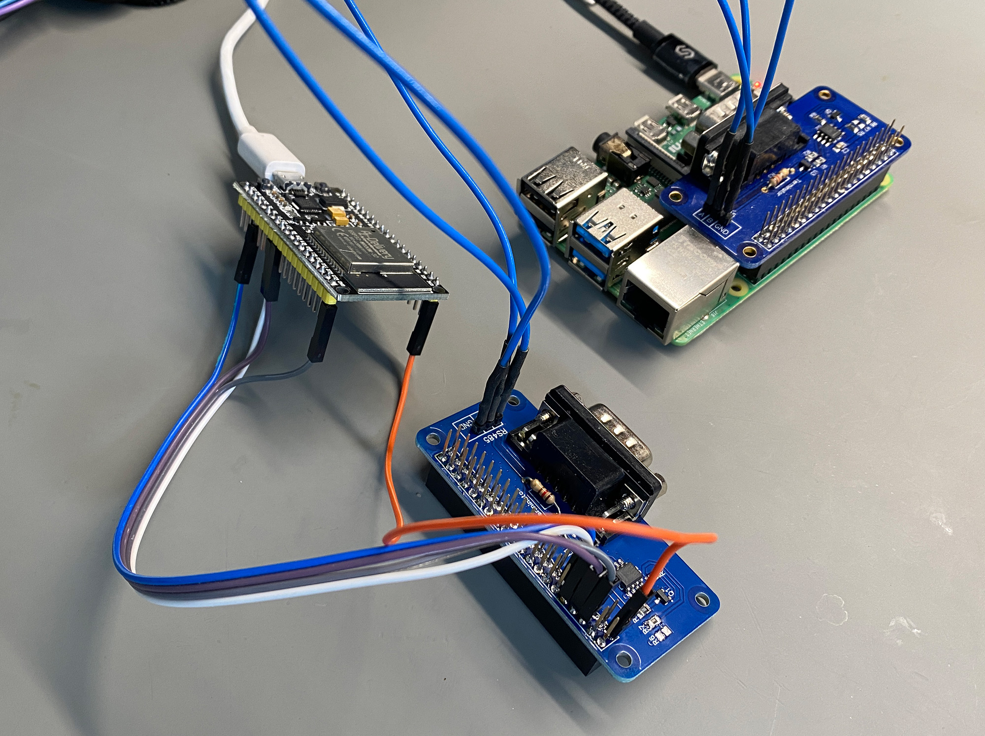
I would like to connect an Rpi (Master) to several esp32's (slaves) via RS485 communication protocol. Currently I use 2x RS485 Pi units to test with, where one is connected to Pi while the other is connected to esp32 (Esp32 Thing Plus, Pin 16 and Pin17). Echoing works fine from Master to slave unit.
My question is, do you have a software example that works with RS485 Pi which uses RS485 addressing? most examples / projects on the internet use MAX485 which has dedicated RE / DE pins but RS485 Pi controls automatically via TXD based on schematic, if i'm not mistaking?
Right now i'm only connected to one slave and both ends fitted with120 Ohm resistors, normal UART communication works and i just need to sort out RS248 communication with dedicated slave addresses.
To make it a little bit more clear i made a wiring diagram.
All inputs will be appriciated,
Thanks in advance
I would like to connect an Rpi (Master) to several esp32's (slaves) via RS485 communication protocol. Currently I use 2x RS485 Pi units to test with, where one is connected to Pi while the other is connected to esp32 (Esp32 Thing Plus, Pin 16 and Pin17). Echoing works fine from Master to slave unit.
echo 1 > /dev/ttyAMA0My question is, do you have a software example that works with RS485 Pi which uses RS485 addressing? most examples / projects on the internet use MAX485 which has dedicated RE / DE pins but RS485 Pi controls automatically via TXD based on schematic, if i'm not mistaking?
Right now i'm only connected to one slave and both ends fitted with120 Ohm resistors, normal UART communication works and i just need to sort out RS248 communication with dedicated slave addresses.
To make it a little bit more clear i made a wiring diagram.
All inputs will be appriciated,
Thanks in advance
28/06/2021
Posted by:
andrew
![]()
Hi
There are several RS485 communication protocols available that support addressing but the most common protocol is Modbus. On the Raspberry Pi side, you can use the MinimalModbus python library with the RS485 Pi. The documentation for MinimalModbus includes examples of how to talk to slave devices. For the slave devices, there should be Modbus libraries available for esp32 modules.
Another option would be to design a simple serial protocol for communicating with your slave devices. To give you an example a few years ago I designed a communication system for a model railway that uses RS485 to communicate between a Raspberry Pi and a range of slave devices using PIC and Atmel microcontrollers.
The communication protocol I used was very simple sending ASCII characters over the serial port. Data packets are variable in length.
Byte 1: STX character 0x02
Byte 2: slave address character 1 - '0' 0x30
Byte 3: slave address character 2 - '1' 0x31
Byte 4: command
Bytes 5+: attributes - variable length where needed
Last Byte: EOT character 0x04
Each slave device would monitor the serial port for any incoming serial data. When it received data it would look for the STX character and set that as the first byte in the packet. When it saw the EOT character it would start processing the packet by checking bytes 2 and 3 to see if they matched the address programmed into the device.
If the address matched it would check the next bytes to see what the command was sent and carry out any actions necessary. It the address did not match the packet would be ignored and the slave would go back to waiting for the STX character.
Once the slave device carried out the action it would send a message back to the master, for example, OK or ERROR. Using this method the slaves would ignore any data packets meant for the master as they would not start with STX or end with EOT.
To give you an example of how this worked in practice the point motors on the model railway could receive three different commands, 1 = move to position one; 2 = move to position two; S = get the status of the point motor. So if you want to move the point motor on address 12 to position 2 you would send the data packet [0x02, 0x30, 0x31, 0x30, 0x04] which in ASCII is [STX, 1, 2, 2, EOT]. The point motor would return the string "POS2" if it succeeds in moving the motor to position 2 or "ERROR" if something went wrong.
The protocol I designed did not have error detection as I could see if something did not work correctly but that would be easy to add in by adding a checksum byte before the EOT character.
Using a ready-made protocol like Modbus will be quicker and allow you to use slave devices that are already designed to work with Modbus but if you only need something simple to talk to a few devices then designing your own serial protocol is a good way to learn about how serial communication works.
29/06/2021
Posted by:
Herant
![]()
Thanks for great response Andrew!
Strictly speaking, I do not need a modbus or RS485 for that matter, the only important thing is that the master can broadcast to the slaves and possibly read data if one of the slaves sends something in return. From what I understand, the RS485 modbus was the only communication protocol that allows bidirectional communications with multiple devices over longer distances.
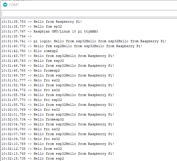
I have tried to follow this (https://roboticsbackend.com/raspberry-pi-arduino-serial-communication/) Bidirectional Serial communication between Raspberry Pi and Arduino, since i use Arduino IDE to program esp32 thing plus, but in order of being able to debug and read serial port on my pc i had to modify the esp32 code to use multiple serial lines at once.
ESP32 Code
Rpi Code
The output i'm getting on esp32 side seems to be correct while on Rpi side doesn't make any sence at all
Strictly speaking, I do not need a modbus or RS485 for that matter, the only important thing is that the master can broadcast to the slaves and possibly read data if one of the slaves sends something in return. From what I understand, the RS485 modbus was the only communication protocol that allows bidirectional communications with multiple devices over longer distances.
I have tried to follow this (https://roboticsbackend.com/raspberry-pi-arduino-serial-communication/) Bidirectional Serial communication between Raspberry Pi and Arduino, since i use Arduino IDE to program esp32 thing plus, but in order of being able to debug and read serial port on my pc i had to modify the esp32 code to use multiple serial lines at once.
ESP32 Code
#include <HardwareSerial.h>

HardwareSerial ser(1);

void setup(){
  Serial.begin(115200);
  ser.begin(115200, SERIAL_8N1, 16, 17);

}

void loop(){
  if(ser.available()){
    String data = ser.readStringUntil('\n');
    Serial.println(data);
    ser.write("Hello from esp32");
    delay(1000);
  }
}
Rpi Code
import serial, time

if __name__ == '__main__':
    ser = serial.Serial('/dev/ttyAMA0', 115200, timeout=1)
    ser.flush()

    while True:
        ser.write(b"Hello from Raspberry Pi!\n")
        line = ser.readline().decode('utf-8', errors="ignore").rstrip()
        print(line)
        time.sleep(1)
The output i'm getting on esp32 side seems to be correct while on Rpi side doesn't make any sence at all
29/06/2021
Posted by:
andrew
![]()
Try slowing down the baud rate to 9600 and see if that makes any difference. It is possible that the clock on the ESP32 does not generate a serial clock of exactly 115200 so if the Raspberry Pi clock does not match the ESP32 clock exactly it would not understand the data it is receiving.
Another possible cause may be the Raspberry Pi is starting the readline() before the transmit buffer has finished sending so it could be picking up parts of the transmitted data. In the Arduino example, the TX and RX pins were connected on separate wires so the communication was full-duplex. The RS485 Pi is half-duplex so it can't transmit and receive at the same time.
You may need to add in some extra code to make sure the transmit buffer is empty before you start listening for any received data. The pyserial library has an out_waiting function which gets the number of bytes in the output buffer. You should be able to use this function to wait until the number of bytes reaches 0 before calling the readline() function.
Do you have an oscilloscope or logic analyser you could use to monitor the TX and RX pins on the Raspberry Pi? This would allow you to see what is being sent and received and help in finding the cause of the problem.
30/06/2021
Posted by:
Herant
![]()
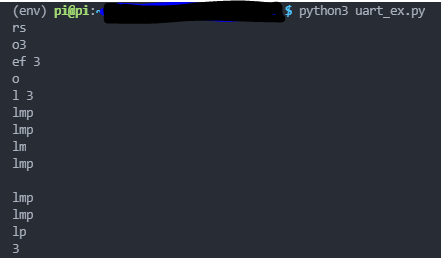
This time i only tried to send from esp32(slave) to Rpi(master). I also changed baud rate to 9600.
ESP32 Code:
Rpi Code:
If i'm getting data from esp32 it only happens once and I'm actually getting a lot errors on pi
Was thinking maybe the bluetooth thingy is the one which disrupt UART such as stated here (https://www.abelectronics.co.uk/kb/article/1035/raspberry-pi-3-serial-port-usage) So i went through this procedure one more time to make sure it was disabled.
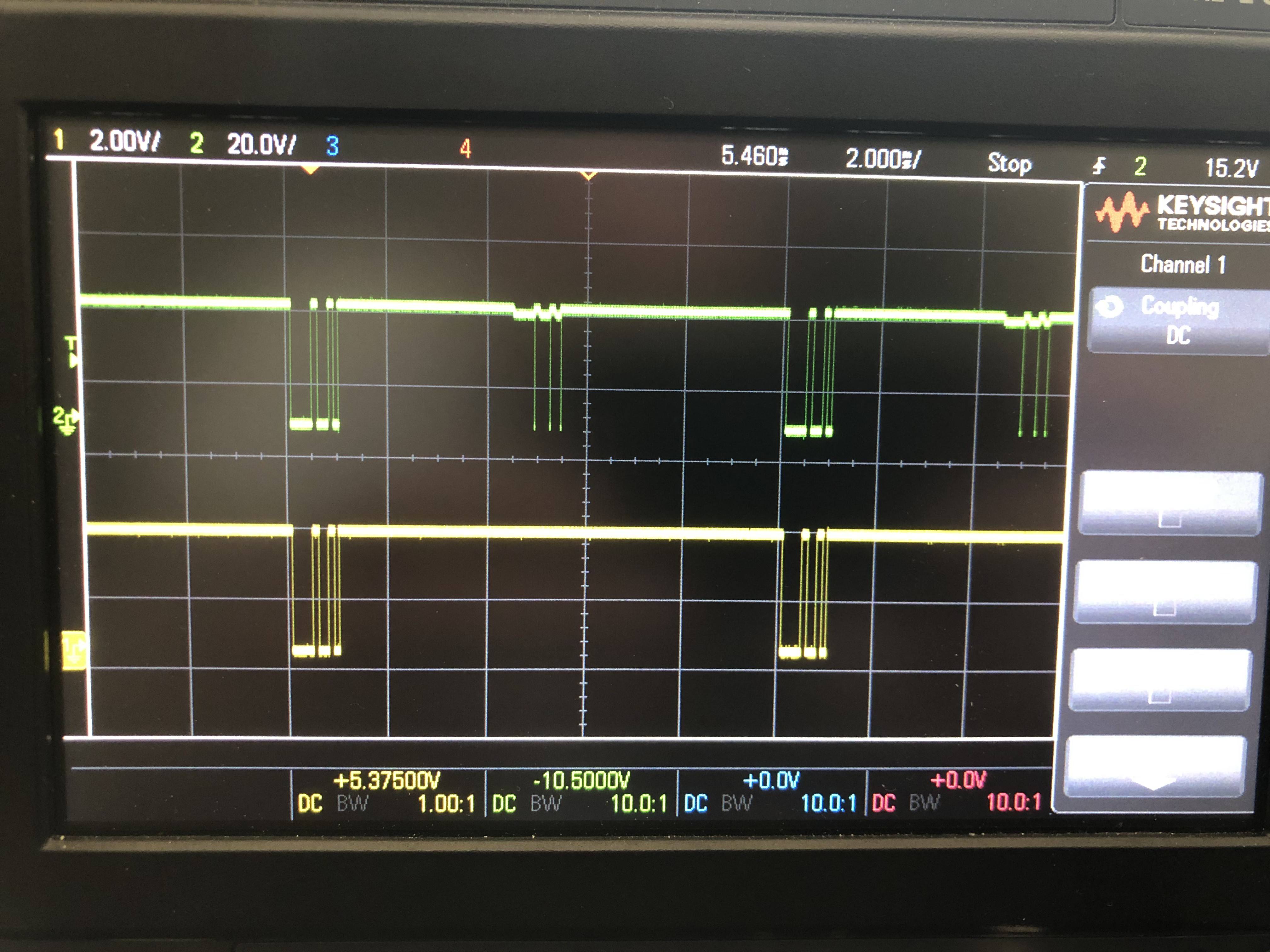
Result from scope:
ESP32 Code:
#include

HardwareSerial ser(1);

void setup(){
  ser.begin(9600, SERIAL_8N1, 16, 17);

}

void loop(){
  ser.write("H");
  delay(10);
}
Rpi Code:
import serial, time
if __name__ == '__main__':
ser = serial.Serial('/dev/serial0', 9600, serial.EIGHTBITS, serial.PARITY_NONE, serial.STOPBITS_ONE)
ser.flush()
while True:
try:
line = ser.readline().decode('utf-8', errors="ignore").rstrip()
print(line)
except IOError as err:
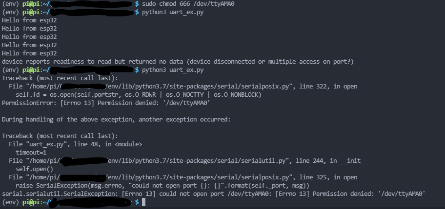
print(err)If i'm getting data from esp32 it only happens once and I'm actually getting a lot errors on pi
device reports readiness to read but returned no data (device disconnected or multiple access on port?)Was thinking maybe the bluetooth thingy is the one which disrupt UART such as stated here (https://www.abelectronics.co.uk/kb/article/1035/raspberry-pi-3-serial-port-usage) So i went through this procedure one more time to make sure it was disabled.
Result from scope:
30/06/2021
Posted by:
andrew
![]()
Try doing a loopback test on the Raspberry Pi by disconnecting the RS485 Pi and connecting the TX and RX pins together so anything transmitted from the Pi will be echoed back to the receive buffer. This will allow you to check if the problem is in the Raspberry Pi UART port.
Have you tested a direct connection between the ESP32 and the Raspberry Pi? If the ESP32 can talk to the Raspberry Pi directly that will suggest a problem with the RS485 Pis.
One other possible cause would be a bad ground connection between the Raspberry Pi and the ESP32 module. Are both devices being powered from a single source or separate power supplies?
30/06/2021
Posted by:
andrew
![]()
Please ignore my previous post.
I tried building the same setup as you are testing with an ESP32 module and two RS485 Pis and I had the same problem as you with the ESP32 receiving data from the Raspberry Pi but not transmitting data back to the Pi.
After testing all of the connections with a logic analyser I found the transmit line on the ESP32 module was not fully pulling the MOSFET Q1 low on the RS485 Pi when it transmitted so the RS485 Pi was staying in receive mode. The output on the logic analyser showed that Q1 did switch off at the end for a fraction of the transmission time so the Raspberry Pi saw some short random spikes which would explain the garbage on the Raspberry Pi end. One possible cause for this could be the TX pin on the ESP32 can not supply enough current to switch the MOSFET.
To fix the problem I modified the RS485 Pi on the ESP32 end by moving the 0R resistor on R6 to the empty R7 pads which isolate the Q1 MOSFET from the transmit pin and connects it instead to GPIO17 (pin 11) on the GPIO header. I then connected pin 11 on the RS485 Pi to GPIO15 on the ESP32 module. This allows the ESP32 to control when the RS485 Pi is in transmit mode by pulling GPIO17 low and high.
I modified the ESP32 code to control the GPIO pin manually before and after a serial write command.
After the ser.write command I added a ser.flush which makes the ESP32 wait for the transmit buffer to empty before setting GPIO15 high.
I tested the modified setup at baud rates up to 115200 and it appears to be working correctly. Hopefully, you can use the same solution on your project.
I tried building the same setup as you are testing with an ESP32 module and two RS485 Pis and I had the same problem as you with the ESP32 receiving data from the Raspberry Pi but not transmitting data back to the Pi.
After testing all of the connections with a logic analyser I found the transmit line on the ESP32 module was not fully pulling the MOSFET Q1 low on the RS485 Pi when it transmitted so the RS485 Pi was staying in receive mode. The output on the logic analyser showed that Q1 did switch off at the end for a fraction of the transmission time so the Raspberry Pi saw some short random spikes which would explain the garbage on the Raspberry Pi end. One possible cause for this could be the TX pin on the ESP32 can not supply enough current to switch the MOSFET.
To fix the problem I modified the RS485 Pi on the ESP32 end by moving the 0R resistor on R6 to the empty R7 pads which isolate the Q1 MOSFET from the transmit pin and connects it instead to GPIO17 (pin 11) on the GPIO header. I then connected pin 11 on the RS485 Pi to GPIO15 on the ESP32 module. This allows the ESP32 to control when the RS485 Pi is in transmit mode by pulling GPIO17 low and high.
I modified the ESP32 code to control the GPIO pin manually before and after a serial write command.
#include
#include

HardwareSerial ser(1);

void setup(){
  pinMode(15, OUTPUT); // Set GPIO15 as digital output pin. Connect to GPIO17 (pin 11) on RS485 Pi header.
  digitalWrite(15, HIGH); // Set GPIO15 high
  Serial.begin(115200);
  ser.begin(115200, SERIAL_8N1, 16, 17);
}

void loop(){
  if(ser.available()){
    String data = ser.readStringUntil('\n');
    Serial.println(data);
    digitalWrite(15, LOW); // Set GPIO15 low
    ser.write("Hello from esp32\n");
    ser.flush(); // wait for the write to complete
    digitalWrite(15, HIGH); // Set GPIO15 high
    delay(1000);
  }
}
After the ser.write command I added a ser.flush which makes the ESP32 wait for the transmit buffer to empty before setting GPIO15 high.
I tested the modified setup at baud rates up to 115200 and it appears to be working correctly. Hopefully, you can use the same solution on your project.
01/07/2021
Posted by:
Herant
![]()
Great stuff Andrew!
I now did just like you described and moved 0R from R6 pad to R7 pad and added GPIO17 pin to one available GPIO on my esp32, and i'm indeed able to recieve data from esp32 now. Do you mind sharing the code you used on Rpi side?
My python program crashes after some time because of
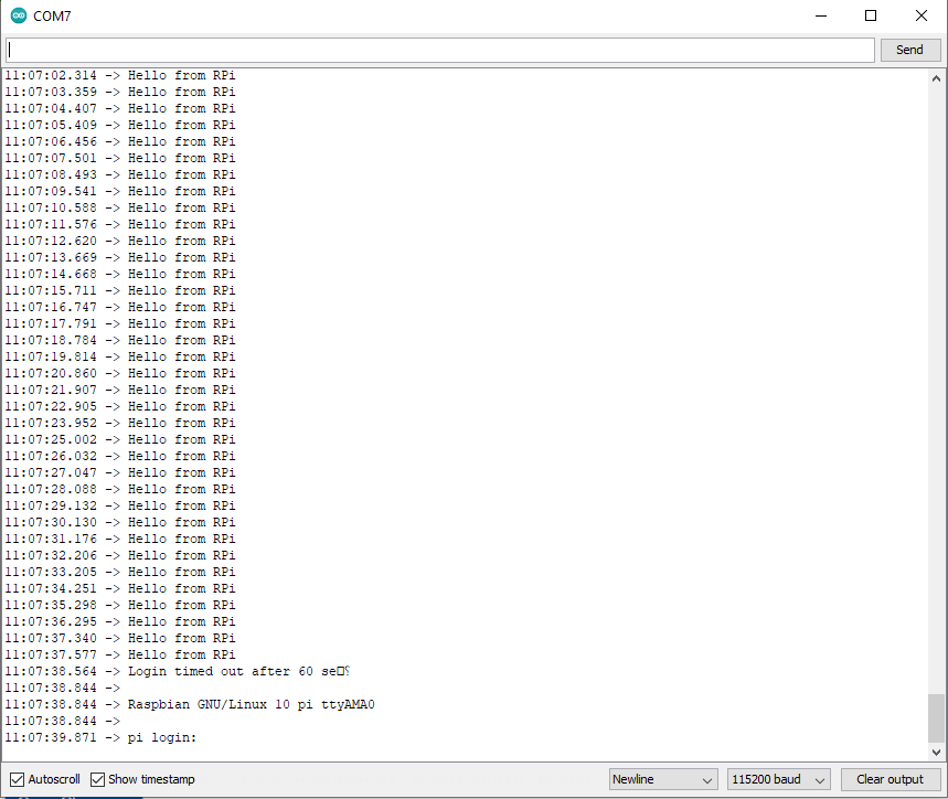
And even though i disabled Linux serial console, after python program crashes esp32 starts getting Linux stuff inside serial monitor.
On top of that i also need to run
before launching a python program which uses PL011. But this is mostly raspberry pi system issues i need to figure out.
Amazing support Andrew!
I now did just like you described and moved 0R from R6 pad to R7 pad and added GPIO17 pin to one available GPIO on my esp32, and i'm indeed able to recieve data from esp32 now. Do you mind sharing the code you used on Rpi side?
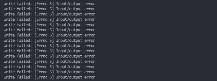
My python program crashes after some time because of
write failed: [Errno 5] Input/output errorAnd even though i disabled Linux serial console, after python program crashes esp32 starts getting Linux stuff inside serial monitor.
On top of that i also need to run
sudo chmod 666 /dev/ttyAMA0before launching a python program which uses PL011. But this is mostly raspberry pi system issues i need to figure out.
Amazing support Andrew!
01/07/2021
Posted by:
andrew
![]()
I'm glad you have working communication between your Raspberry Pi and ESP32 module.
The Raspberry Pi code I used was the program you posted in your second post.
The error you are getting looks like something is trying to access the serial port at the same time as your program. In your /boot/cmdline.txt file are there any references to ttyS0, serial0 or ttyAMA0? If there are remove them and that should fix the problem.
If that is not the issue then there may be another process running that is trying to send data to the serial port.
The Raspberry Pi code I used was the program you posted in your second post.
import serial, time

if __name__ == '__main__':
    ser = serial.Serial('/dev/ttyAMA0', 115200, timeout=1)
    ser.flush()

    while True:
        ser.write(b"Hello from Raspberry Pi!\n")
        line = ser.readline().decode('utf-8', errors="ignore").rstrip()
        print(line)
        time.sleep(1)
The error you are getting looks like something is trying to access the serial port at the same time as your program. In your /boot/cmdline.txt file are there any references to ttyS0, serial0 or ttyAMA0? If there are remove them and that should fix the problem.
If that is not the issue then there may be another process running that is trying to send data to the serial port.
04/07/2021
Posted by:
Herant
![]()
My /boot/cmdline.txt currently looks like this
/boot/config.txt
My current script works a lot better and also helped me narrow down the issue which seems to be when Rpi is transmitting. I also moved resistor on RS485 Pi which sits on Rpi to be able to gain better control over when to enter transmitter or reciever mode.
Rpi code
Arduino code
So as long as i only send from Pi to esp32 everything works fine, once i trigger "Echo" such that esp32 goes into transmitter mode and Pi tries to recieve, the data gets corrupted and the only way to fix it is to restart python program. The wierd thing is that this is not happening everytime.
While running the program i checked which of the processess where using /dev/ttyAMA0 and it looked like that the python was the only one.

root=/dev/mmcblk0p7 rootfstype=ext4 elevator=deadline fsck.repair=yes rootwait/boot/config.txt
# For more options and information see
# http://rpf.io/configtxt
# Some settings may impact device functionality. See link above for details

# uncomment if you get no picture on HDMI for a default "safe" mode
#hdmi_safe=1

# uncomment this if your display has a black border of unused pixels visible
# and your display can output without overscan
disable_overscan=1

# uncomment the following to adjust overscan. Use positive numbers if console
# goes off screen, and negative if there is too much border
#overscan_left=16
#overscan_right=16
#overscan_top=16
#overscan_bottom=16

# uncomment to force a console size. By default it will be display's size minus
# overscan.
#framebuffer_width=1280
#framebuffer_height=720

# uncomment if hdmi display is not detected and composite is being output
hdmi_force_hotplug=1

# uncomment to force a specific HDMI mode (this will force VGA)
hdmi_group=1
hdmi_mode=16

# uncomment to force a HDMI mode rather than DVI. This can make audio work in
# DMT (computer monitor) modes
#hdmi_drive=2

# uncomment to increase signal to HDMI, if you have interference, blanking, or
# no display
#config_hdmi_boost=4

# uncomment for composite PAL
#sdtv_mode=2

#uncomment to overclock the arm. 700 MHz is the default.
#arm_freq=800

# Uncomment some or all of these to enable the optional hardware interfaces
dtparam=i2c_arm=on
#dtparam=i2s=on
dtparam=spi=on

# Uncomment this to enable infrared communication.
#dtoverlay=gpio-ir,gpio_pin=17

# Additional overlays and parameters are documented /boot/overlays/README

# Enable audio (loads snd_bcm2835)
dtparam=audio=on

[pi4]
# Enable DRM VC4 V3D driver on top of the dispmanx display stack
dtoverlay=vc4-fkms-v3d
max_framebuffers=2

[all]
#dtoverlay=vc4-fkms-v3d

# NOOBS Auto-generated Settings:
start_x=1
gpu_mem=128
enable_uart=1
dtoverlay=w1-gpio
dtoverlay=disable-bt
#core_freq=250
force_turbo=1
avoid_warnings=1
My current script works a lot better and also helped me narrow down the issue which seems to be when Rpi is transmitting. I also moved resistor on RS485 Pi which sits on Rpi to be able to gain better control over when to enter transmitter or reciever mode.
Rpi code
import time
import serial
import RPi.GPIO as GPIO

GPIO.setwarnings(False)
GPIO.setmode(GPIO.BOARD)
GPIO.setup(11, GPIO.OUT, initial=GPIO.LOW)

ser = serial.Serial(
    port='/dev/serial0',
    baudrate = 115200,
    parity=serial.PARITY_NONE,
    stopbits=serial.STOPBITS_ONE,
    bytesize=serial.EIGHTBITS,
    timeout=1.5
)

ser.flush()

while True:
    try:
        usr = input(">>> ")
        b = bytes(str(usr), encoding='utf-8')
        ser.write(b)
        ser.flush()

        GPIO.output(11, 1)
        tdata = ser.readall()
        if(tdata):
            #time.sleep(1)
            data_left = ser.inWaiting()
            tdata += ser.read(data_left)
            print(tdata)
        GPIO.output(11, 0)
        ser.flush()

    except ValueError as error:
        print(error)

    except IOError as error:
        print(error)
Arduino code
#include

HardwareSerial ser(1);

int enablePin = 13;

void setup()
{
  Serial.begin(115200);
  ser.begin(115200, SERIAL_8N1, 16, 17);
  pinMode(enablePin, OUTPUT);
  digitalWrite(enablePin, HIGH);
}

void loop()

{
  while (ser.available())
     {
        String stringData = ser.readStringUntil('\n');
        if(stringData != ""){
          Serial.println("Received: " + stringData);
        }
        if(stringData == "Echo"){
          digitalWrite(enablePin, LOW);
          ser.write("Hello from esp32");
          ser.flush();
          Serial.println("Transmitting: Hello from esp32");
          digitalWrite(enablePin, HIGH);
        }
    }
 }
So as long as i only send from Pi to esp32 everything works fine, once i trigger "Echo" such that esp32 goes into transmitter mode and Pi tries to recieve, the data gets corrupted and the only way to fix it is to restart python program. The wierd thing is that this is not happening everytime.
While running the program i checked which of the processess where using /dev/ttyAMA0 and it looked like that the python was the only one.
05/07/2021
Posted by:
andrew
![]()
I tried running your code on a Pi and ESP32 and it appeared to be working on my setup as you can see from the screenshot below.
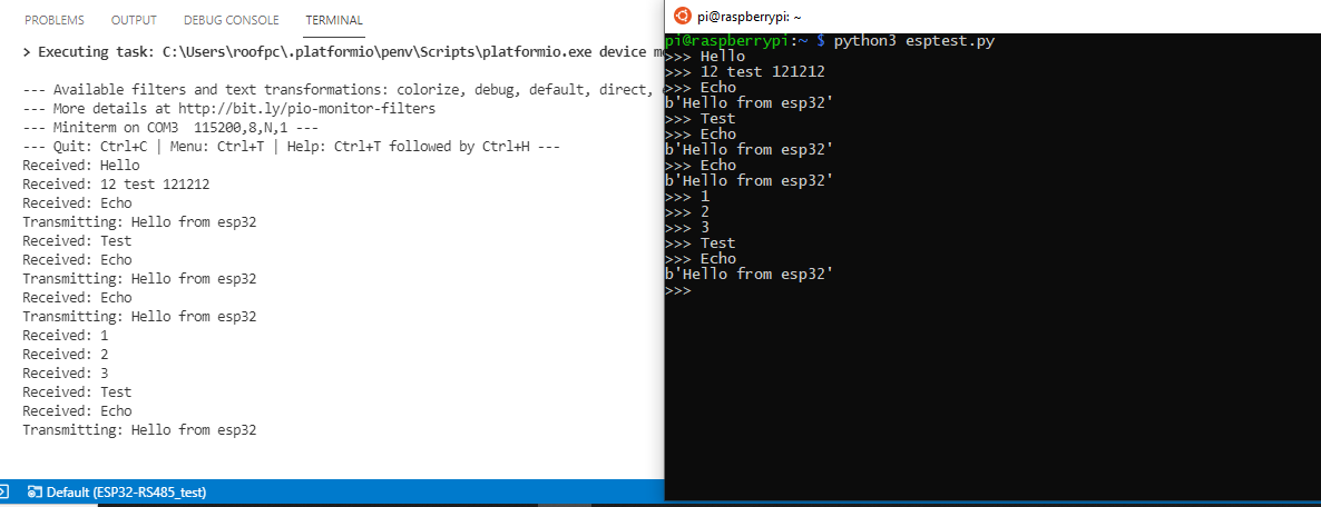
I tried changing my config.txt file to match yours but I could not replicate the issue so the only thing I can think of is you have another process that is opening and closing the serial port and it is occasionally conflicting with your python program. The lsof command would only show the process if it is open at exactly the same time as you run the command.
I did notice a couple of potential issues with your code that could be contributing to the problem.
In your python program, you are changing the GPIO state around the serial read instead of write so the RS485 Pi is spending most of its time in transmit mode. You can see this on the capture from my logic analyser.
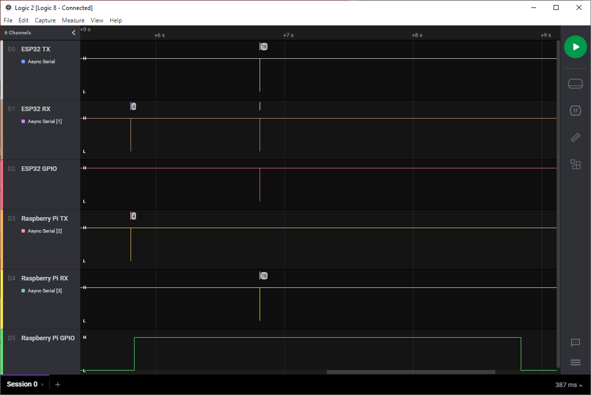
I changed your python program to put the GPIO state changes around the write command and changed the read command to read_until so it will keep reading until it sees a new line character. In the ESP32 code, I added a new line character to the end of the response string. In the python program, I also added a new line character to the end of the write string so the ESP32 will send a response immediately instead of waiting for the serial read to timeout.
Python Code
ESP32 Code
This reduces the time the program takes to respond from over 1 second to less than 2 milliseconds which then caused a new problem. As you can see in the screenshot below the response was sent back from the ESP32 before the python program set the GPIO pin high so the RS485 Pi on the Raspberry Pi was still in transmit mode when the ESP32 sent its response and it was missed by the python program.
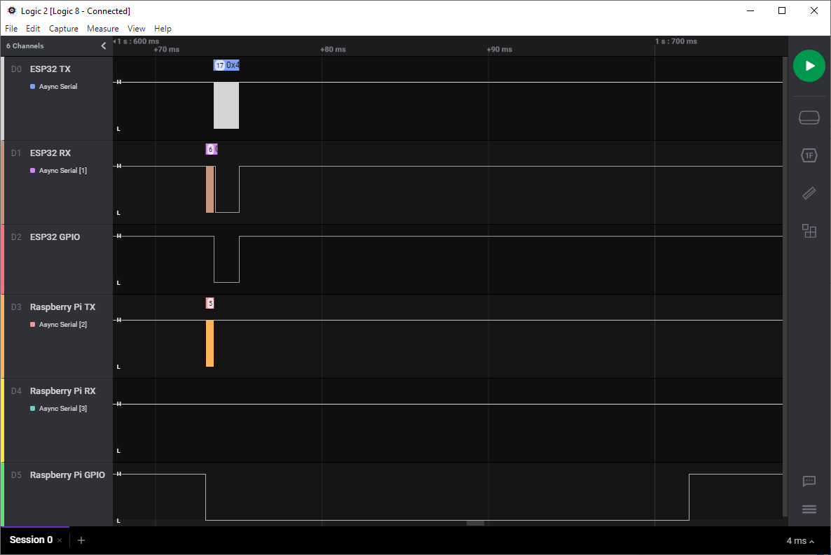
To get around this issue I added a 40ms delay before the ESP32 responds to the Echo command which as you can see from the screenshot below is just enough time for the python program to go back into receive mode.
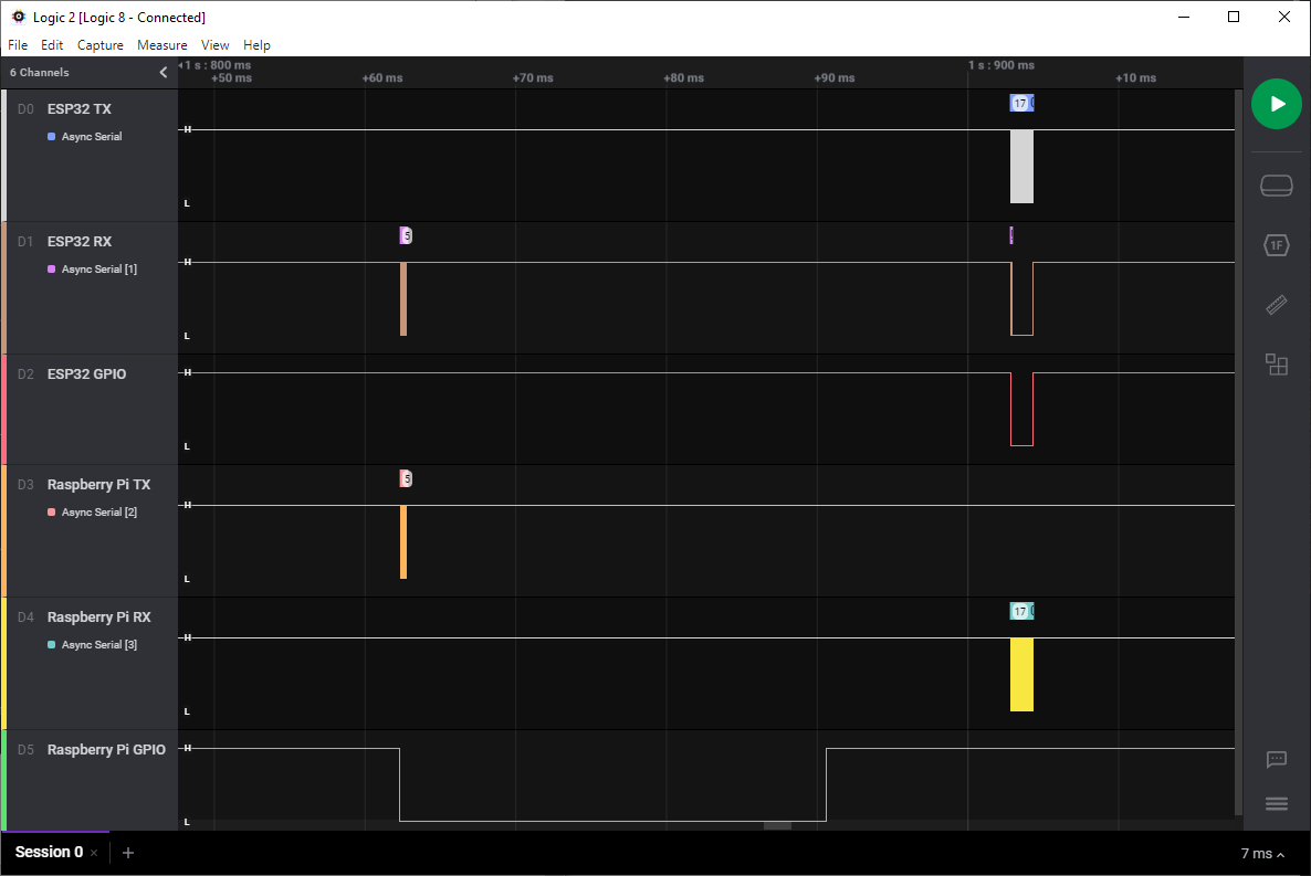
Writing your Raspberry Pi program in a compiled language like C would probably reduce the time it takes for the GPIO pin to go high after a serial write but for now, the 40ms delay in the ESP32 code will allow you to keep using python.
Can you try these updated programs on your Raspberry Pi and ESP32 modules and see if this helps to solve the problems you are getting?
I tried changing my config.txt file to match yours but I could not replicate the issue so the only thing I can think of is you have another process that is opening and closing the serial port and it is occasionally conflicting with your python program. The lsof command would only show the process if it is open at exactly the same time as you run the command.
I did notice a couple of potential issues with your code that could be contributing to the problem.
In your python program, you are changing the GPIO state around the serial read instead of write so the RS485 Pi is spending most of its time in transmit mode. You can see this on the capture from my logic analyser.
I changed your python program to put the GPIO state changes around the write command and changed the read command to read_until so it will keep reading until it sees a new line character. In the ESP32 code, I added a new line character to the end of the response string. In the python program, I also added a new line character to the end of the write string so the ESP32 will send a response immediately instead of waiting for the serial read to timeout.
Python Code
import time
import serial
import RPi.GPIO as GPIO

GPIO.setwarnings(False)
GPIO.setmode(GPIO.BOARD)
GPIO.setup(11, GPIO.OUT, initial=GPIO.LOW)
GPIO.output(11, 1)

ser = serial.Serial(
    port='/dev/serial0',
    baudrate = 115200,
    parity=serial.PARITY_NONE,
    stopbits=serial.STOPBITS_ONE,
    bytesize=serial.EIGHTBITS,
    timeout=1.5
)

ser.flush()


while True:
    try:
        usr = input(">>> ")
        b = bytes(str(usr + "\n"), encoding='utf-8')
        GPIO.output(11, 0)
        ser.write(b)
        ser.flush()
        GPIO.output(11, 1)

        line = ser.read_until().decode('utf-8', errors="ignore").rstrip()
        print(line)

    except ValueError as error:
        print(error)

    except IOError as error:
        print(error)
ESP32 Code
#include
#include

HardwareSerial ser(1);

int enablePin = 13;

void setup()
{
  Serial.begin(115200);
  ser.begin(115200, SERIAL_8N1, 16, 17);
  pinMode(enablePin, OUTPUT);
  digitalWrite(enablePin, HIGH);
}

void loop()

{
  while (ser.available())
     {
        String stringData = ser.readStringUntil('\n');
        if(stringData != ""){
          Serial.println("Received: " + stringData);
        }
        if(stringData == "Echo"){
          delayMicroseconds(40000); // delay 40ms for python to set the GPIO low on the Pi
          digitalWrite(enablePin, LOW);
          ser.write("Hello from esp32\n");
          ser.flush();
          Serial.println("Transmitting: Hello from esp32");
          digitalWrite(enablePin, HIGH);
        }
    }
 }
This reduces the time the program takes to respond from over 1 second to less than 2 milliseconds which then caused a new problem. As you can see in the screenshot below the response was sent back from the ESP32 before the python program set the GPIO pin high so the RS485 Pi on the Raspberry Pi was still in transmit mode when the ESP32 sent its response and it was missed by the python program.
To get around this issue I added a 40ms delay before the ESP32 responds to the Echo command which as you can see from the screenshot below is just enough time for the python program to go back into receive mode.
Writing your Raspberry Pi program in a compiled language like C would probably reduce the time it takes for the GPIO pin to go high after a serial write but for now, the 40ms delay in the ESP32 code will allow you to keep using python.
Can you try these updated programs on your Raspberry Pi and ESP32 modules and see if this helps to solve the problems you are getting?
05/07/2021
Posted by:
Herant
![]()
Another amazing response from you Andrew!
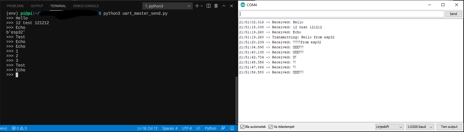
I tried to run the code as you suggested, but there was no difference. That was when I became more and more suspicious if there was something wrong with the Pi, luckily I had an Rpi 3 Model B lying around. After I hooked everything up, removed console=tty from /boot/cmdline.txt and disabled the linux console, the script and bi-directional communication just worked.
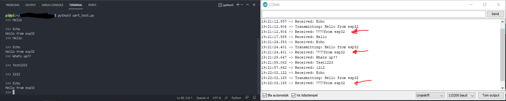
One thing I noticed, which is different from your screenshot, is that my esp32 receives the same data right after it sends "Echo" (marked on the image with red arrows) Or the data becomes a bit corrupted since it receives the backward question marks at the beginning of the string. Any idea why that happens?
Thinking that I will first try to set up Raspbian again before I possibly get a new Rpi4.
I tried to run the code as you suggested, but there was no difference. That was when I became more and more suspicious if there was something wrong with the Pi, luckily I had an Rpi 3 Model B lying around. After I hooked everything up, removed console=tty from /boot/cmdline.txt and disabled the linux console, the script and bi-directional communication just worked.
One thing I noticed, which is different from your screenshot, is that my esp32 receives the same data right after it sends "Echo" (marked on the image with red arrows) Or the data becomes a bit corrupted since it receives the backward question marks at the beginning of the string. Any idea why that happens?
Thinking that I will first try to set up Raspbian again before I possibly get a new Rpi4.
05/07/2021
Posted by:
andrew
![]()
I'm not sure what is causing the backward question marks. Try increasing the 40ms delay on the ESP32 code. It could be that as the Pi 3 is slower it is taking longer for Python to change the GPIO state so the data is somehow getting corrupted.
If that does not work try a new setup of Raspbian and see if that solves the problem.
If that does not work try a new setup of Raspbian and see if that solves the problem.
06/07/2021
Posted by:
Herant
![]()
After reinstalling new version of Raspbian or Raspberry Pi OS, and configuring according to this KB page everything just works perfectly and i can finally concentrate on writing code for the communication.
Instead of using the modbus package, I plan to create a simple script with similar steps as you suggested in the beginning. Instead of sending byte array I thought i would wrap data inside a json object, the object only needs to contain an address and command as far as I can see. For now, I do not think it is necessary with STX and EOT but is easy to add if i suddenly need these.
Thank you so much for the wonderful help
Note: documents in Portable Document Format (PDF) require Adobe Acrobat Reader 5.0 or higher to view.
Download Adobe Acrobat Reader or other PDF reading software for your computer or mobile device.