
Newb: IO Pi Plus, Raspberry Pi 2+ - can't see board
The IO Pi Plus is a 32 channel MCP23017 GPIO expander for the Raspberry Pi
15/11/2022
Posted by:
Andy_hollywood
![]()
Hello Everyone,
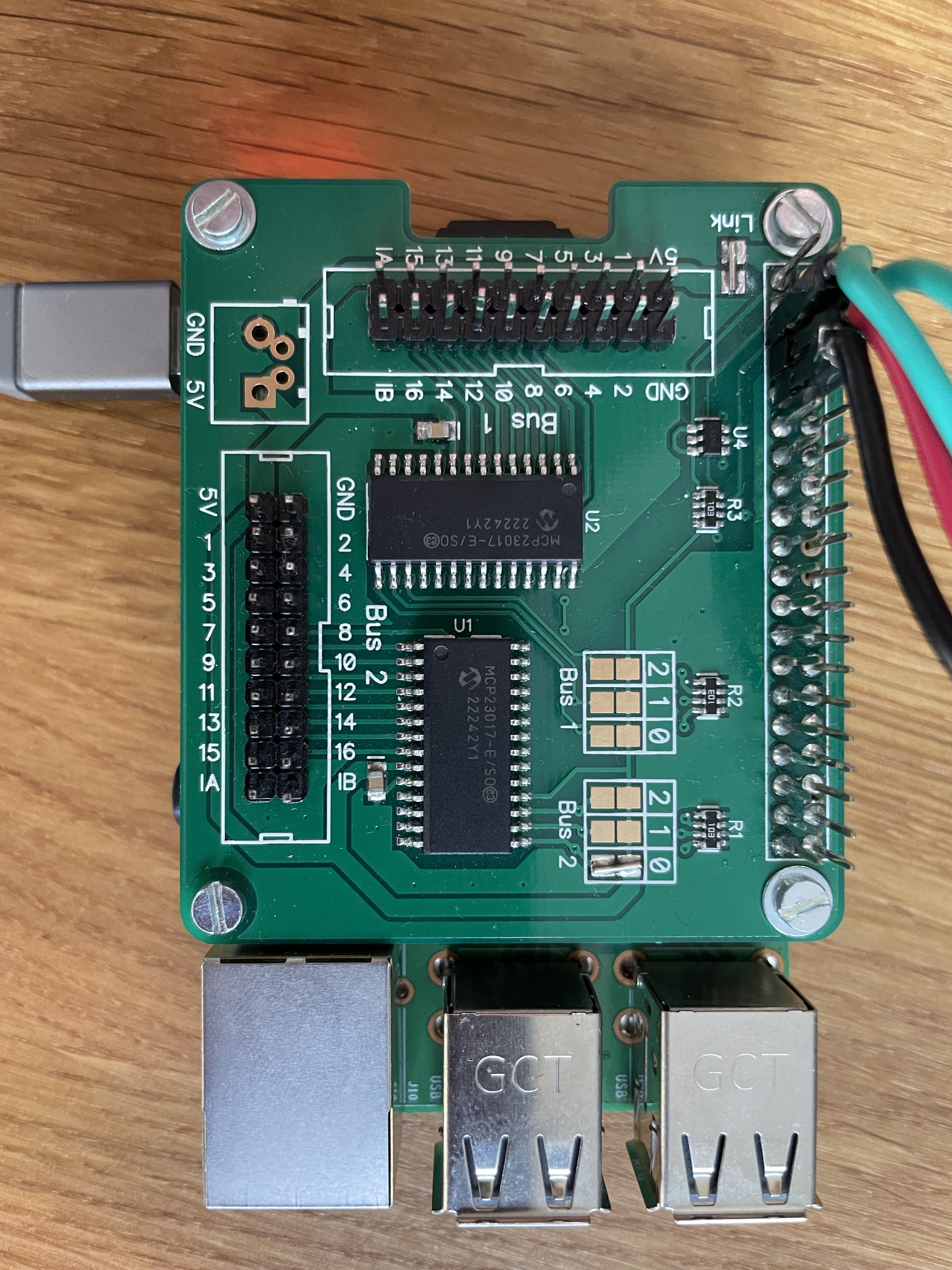
I'm just getting started with the Pi and indeed i2C, I have bought the "IO Pi Plus", soldered on the connections and mounted it on top of my Pi2+,
followed the instructions here (https://www.abelectronics.co.uk/kb/article/23/python-library-and-demos and here https://www.abelectronics.co.uk/kb/article/1/i2c-part-2---enabling-i-c-on-the-raspberry-pi) and now with the baord connected running:
I have enabled i2c on the pi... not sure how to debug it.
I have checked with my meter that the board has power from 5v -> gnd on both buses and the other terminals...
Wondered if there was anything obvious i should try?
As an aside - i added a power button on teh GPIO pins on the GPIO extension pins on the IO Pi Plus which appears to work great - so feel the board is getting power...
Any ideas?
I'm just getting started with the Pi and indeed i2C, I have bought the "IO Pi Plus", soldered on the connections and mounted it on top of my Pi2+,
followed the instructions here (https://www.abelectronics.co.uk/kb/article/23/python-library-and-demos and here https://www.abelectronics.co.uk/kb/article/1/i2c-part-2---enabling-i-c-on-the-raspberry-pi) and now with the baord connected running:
pi@seeburg:~ $ sudo i2cdetect -y 1
     0  1  2  3  4  5  6  7  8  9  a  b  c  d  e  f
00:                         -- -- -- -- -- -- -- --
10: -- -- -- -- -- -- -- -- -- -- -- -- -- -- -- --
20: -- -- -- -- -- -- -- -- -- -- -- -- -- -- -- --
30: -- -- -- -- -- -- -- -- -- -- -- -- -- -- -- --
40: -- -- -- -- -- -- -- -- -- -- -- -- -- -- -- --
50: -- -- -- -- -- -- -- -- -- -- -- -- -- -- -- --
60: -- -- -- -- -- -- -- -- -- -- -- -- -- -- -- --
70: -- -- -- -- -- -- -- --
I have enabled i2c on the pi... not sure how to debug it.
I have checked with my meter that the board has power from 5v -> gnd on both buses and the other terminals...
Wondered if there was anything obvious i should try?
As an aside - i added a power button on teh GPIO pins on the GPIO extension pins on the IO Pi Plus which appears to work great - so feel the board is getting power...
Any ideas?
15/11/2022
Posted by:
andrew
![]()
Hello Andy
In the photo, it looks like you have a green wire connected to pin 5 on the GPIO header. What is this wire being used for? The IO Pi Plus uses pins 3 and 5 for the I2C bus so if you have any external connections to either of those pins it can stop the I2C bus from working correctly.
In the photo, it looks like you have a green wire connected to pin 5 on the GPIO header. What is this wire being used for? The IO Pi Plus uses pins 3 and 5 for the I2C bus so if you have any external connections to either of those pins it can stop the I2C bus from working correctly.
15/11/2022
Posted by:
Andy_hollywood
![]()
Ah so those wires are for a power switch, and its LED - so i can turn it on and off....
GPIO 3 (PIn 5) is the switch, GPIO 4 (pin 5) and PIn 6 is turning on and off the LED..
So sounds like i've been over zleaous on that - hadn't realised pins 3 and 5... i'll remove those and see what gives.
Thanks for your help.
GPIO 3 (PIn 5) is the switch, GPIO 4 (pin 5) and PIn 6 is turning on and off the LED..
#!/usr/bin/env python

import RPi.GPIO as GPIO
import subprocess
import time

GPIO.setmode(GPIO.BCM)
GPIO.setup(3, GPIO.IN, pull_up_down=GPIO.PUD_UP)

GPIO.setup(4, GPIO.OUT);
GPIO.output(4, GPIO.HIGH);

GPIO.wait_for_edge(3, GPIO.FALLING)
time.sleep(5)

GPIO.output(4, GPIO.LOW)
subprocess.call(['shutdown', '-h', 'now'], shell=False)
So sounds like i've been over zleaous on that - hadn't realised pins 3 and 5... i'll remove those and see what gives.
Thanks for your help.
15/11/2022
Posted by:
Andy_hollywood
![]()
So this worked. I removed my little service so it freed up the pins.
and voila! All working a treat.
thanks so much!
and voila! All working a treat.
thanks so much!
27/03/2023
Posted by:
AntonioCraig
![]()
Note: documents in Portable Document Format (PDF) require Adobe Acrobat Reader 5.0 or higher to view.
Download Adobe Acrobat Reader or other PDF reading software for your computer or mobile device.