The AB Electronics UK Knowledge Base provides support solutions, tutorials and troubleshooting guides.

YOU WILL NEED THIS BOARD
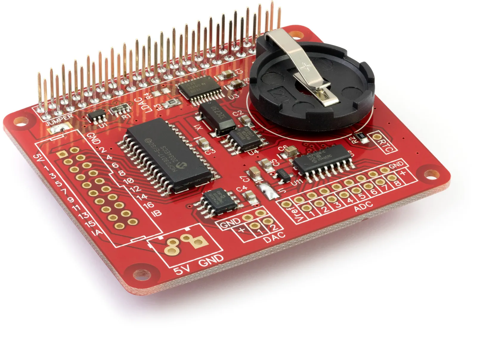
Node.js Library to use with Expander Pi Raspberry Pi development board.
Note: Microchip recommends that digital pins 8 (GPA7) and 16 (GPB7) are used as outputs only. This change was made for revision D MCP23017 chips manufactured after June 2020. See the MCP23017 datasheet for more information.
Install
To download to your Raspberry Pi type in the terminal:
git clone https://github.com/abelectronicsuk/ABElectronics_NodeJS_Libraries.git
The IO Pi library is located in the /lib/expanderpi/ directory
The example files are located in the /examples/expanderpi/ directory
The Expander Pi library requires the rpio and i2c-bus libraries to run.
Install rpio from npm package repository rpio with
npm install rpio
Install i2c-bus from npm package repository i2c-bus with
npm install i2c-bus
The Expander Pi library is split up into four classes, ADC, DAC, IO and RTC.
Expander Pi ADC
The ExpanderPiADC class controls the MCP3208 12-bit ADC.
ADC Functions
readADCVoltage(channel, mode)
Read the voltage from the selected channel on the ADC
Parameters: channel - 1 or 2; mode - 0 = single-ended, 1 = differential
Returns: number as a float between 0 and 2.048
readADCRaw(channel, mode)
Read the raw value from the selected channel on the ADC
Parameters: channel - 1 or 2; mode - 0 = single-ended, 1 = differential
Returns: int
setADCRefVoltage(voltage)
Set the reference voltage for the analogue to digital converter.
The ADC uses the raspberry pi 3.3V power as a voltage reference so using this method to set the reference to match the exact output voltage from the 3.3V regulator will increase the accuracy of the ADC readings.
Parameters: voltage - float between 0.0 and 7.0
Returns: null
ADC Usage
To use the ExpanderPiADC class in your code you must first import the Expander Pi library:
var expanderpi = require('../../lib/expanderpi/expanderpi');
Next you must initialise the ExpanderPiADC object:
var adc = new ExpanderPiADC();
Set the reference voltage.
adc.setADCRefVoltage(4.096);
Read the voltage from channel 1 and display it on the screen
console.log('Reading 1 Voltage: ' + adc.readADCVoltage(1, 0));
Expander Pi DAC
The ExpanderPiDAC class controls the MCP4822 12-bit DAC.
DAC Functions
setDACVoltage(channel, voltage)
Set the voltage for the selected channel on the DAC. The DAC has two gain values, 1 or 2, which can be set when the ADCDAC object is created. A gain of 1 will give a voltage between 0 and 2.047 volts. A gain of 2 will give a voltage between 0 and 4.096 volts.
Parameters: channel - 1 or 2, voltage - sets the voltage for the selected channel.
Returns: null
setDACRaw(channel, value)
Set the raw value from the selected channel on the DAC
Parameters: channel - 1 or 2, value - int between 0 and 4095
Returns: null
setDACGain(gain)
Set the gain for the DAC. This is used to set the output based on the reference voltage of 2.048V.
When the gain is set to 2 the maximum voltage will be approximately 4.096V.
Parameters: gain - 1 or 2
Returns: null
DAC Usage
To use the ExpanderPiDAC class in your code you must first import the Expander Pi library:
var expanderpi = require('../../lib/expanderpi/expanderpi');
Next, you must initialise the ExpanderPiDAC object:
var dac = new ExpanderPiDAC();
Set the DAC gain to be 1
dac.setDACGain(1);
Set the voltage on channel 1 as 0.8V and channel 2 as 1.5V.
dac.setDACVoltage(1, 0.8);
dac.setDACVoltage(2, 1.5);
ExpanderPi IO
The ExpanderPiIO class controls the MCP23017 16-pin I/O controller.
IO Functions
setPinDirection(pin, direction):
Sets the IO direction for an individual pin
Parameters: pin - 1 to 16, direction - 1 = input, 0 = output
Returns: null
setPortDirection(port, direction):
Sets the IO direction for the specified IO port
Parameters: port - 0 = pins 1 to 8, port 1 = pins 9 to 16, direction - 1 = input, 0 = output
Returns: null
setPinPullup(pin, value)
Set the internal 100K pull-up resistors for an individual pin Parameters: pin - 1 to 16, value: 1 = Enabled, 0 = Disabled
Returns: null
setPortPullups(port, value)
Set the internal 100K pull-up resistors for the selected IO port
Parameters: port - 0 or 1, value: 0x00 to 0xFF
Returns: null
writePin(pin, value)
Write to an individual pin 1 - 16
Parameters: pin - 1 to 16, value - 1 = Enabled, 0 = Disabled
Returns: null
writePort(self, port, value)
Write to all pins on the selected port
Parameters: port - 0 = pins 1 to 8, port 1 = pins 9 to 16, value - number between 0 and 255 or 0x00 and 0xFF
Returns: null
readPin(pin)
Read the value of an individual pin 1 - 16
Parameters: pin: 1 to 16
Returns: 0 = logic level low, 1 = logic level high
readPort(port)
Read all pins on the selected port
Parameters: port - 0 = pins 1 to 8, port 1 = pins 9 to 16
Returns: number between 0 and 255 or 0x00 and 0xFF
invertPort(port, polarity)
Invert the polarity of the pins on a selected port
Parameters: port - 0 = pins 1 to 8, port 1 = pins 9 to 16, polarity - 0 = same logic state of the input pin, 1 = inverted logic state of the input pin
Returns: null
invertPin(pin, polarity)
Invert the polarity of the selected pin
Parameters: pin - 1 to 16, polarity - 0 = same logic state of the input pin, 1 = inverted logic state of the input pin Returns: null
mirrorInterrupts(value)
Mirror Interrupts
Parameters: value - 1 = The INT pins are internally connected, 0 = The INT pins are not connected. INTA is associated with PortA and INTB is associated with PortB
Returns: null
setInterruptType(port, value)
Sets the type of interrupt for each pin on the selected port
Parameters: port 0 = pins 1 to 8, port 1 = pins 9 to 16, value: 1 = interrupt is fired when the pin matches the default value, 0 = the interrupt is fired on state change
Returns: null
setInterruptPolarity(value)
This sets the polarity of the INT output pins Parameters: 1 = Active-high, 0 = Active-low Returns: null
setInterruptDefaults(port, value)
These bits set the compare value for pins configured for interrupt-on-change on the selected port.
If the associated pin level is the opposite of the register bit, an interrupt occurs.
Parameters: port 0 = pins 1 to 8, port 1 = pins 9 to 16, value: compare value
Returns: null
setInterruptOnPort(port, value)
Enable interrupts for the pins on the selected port
Parameters: port 0 = pins 1 to 8, port 1 = pins 9 to 16, value: number between 0 and 255 or 0x00 and 0xFF
Returns: null
setInterruptOnPin(pin, value)
Enable interrupts for the selected pin
Parameters: pin - 1 to 16, value - 0 = interrupt disabled, 1 = interrupt enabled
Returns: null
readInterruptStatus(port)
Read the interrupt status for the pins on the selected port
Parameters: port 0 = pins 1 to 8, port 1 = pins 9 to 16
Returns: status
readInterruptCapture(port)
Read the value from the selected port at the time of the last interrupt trigger
Parameters: port 0 = pins 1 to 8, port 1 = pins 9 to 16
Returns: status
resetInterrupts()
Set the interrupts A and B to 0
Parameters: null
Returns: null
IO Usage
To use the ExpanderPiIO class in your code you must first import the Expander Pi library:
var expanderpi = require('../../lib/expanderpi/expanderpi');
Next, you must initialise the ExpanderPiIO object
var bus = new ExpanderPiIO();
We will read the inputs 1 to 8 from bus 1 so set port 0 as inputs and enable the internal pull-up resistors
bus.setPortDirection(0, 0xFF);
bus.setPortPullups(0, 0xFF);
You can now read pin 1 with:
console.log('Pin 1: %d', bus.readPin(1));
ExpanderPi RTC
The ExpanderPiRTC class controls the DS1307 real-time clock.
RTC Functions:
setDate(date)
Set the date and time on the RTC using a javascript Date object
Parameters: date
Returns: null
readDate()
Returns the date from the RTC as a javascript Date object
Returns: date object
enableOutput()
Enable the square-wave output on the SQW pin.
Returns: null
disableOutput()
Disable the square-wave output on the SQW pin.
Returns: null
setFrequency(frequency)
Set the frequency for the square-wave output on the SQW pin.
Parameters: frequency - options are: 1 = 1Hz, 2 = 4.096KHz, 3 = 8.192KHz, 4 = 32.768KHz
Returns: null
writeMemory(address, valuearray)
Write to the memory on the DS1307. The DS1307 contains 56 - Byte, battery-backed RAM with Unlimited Writes
Parameters: address - 0x08 to 0x3F
Parameters: valuearray - byte array (Uint8Array) containing data to be written to memory
Returns: null
readMemory(address, valuearray)
Read from the memory on the DS1307. The DS1307 contains 56 - Byte, battery-backed RAM with Unlimited Writes
Parameters: address - 0x08 to 0x3F
Parameters: length - Up to 32 bytes. length can not exceed the available address space.
Returns: Returns a Uint8Array type array of the data read from memory
RTC Usage
To use the ExpanderPiRTC class in your code you must first import the Expander Pi library:
var expanderpi = require('../../lib/expanderpi/expanderpi');
Next, you must create an ExpanderPiRTC object:
var rtc = new ExpanderPiRTC();
Set the current time using a date object:
var d = new Date(2016, 07, 04, 10, 23, 00, 00);
rtc.setDate(d);
Enable the square-wave output at 8.192KHz on the SQW pin:
rtc.set_frequency(3)
rtc.enable_output()
Read the current date and time from the RTC at 1-second intervals:
var myClock = setInterval(clockTimer, 1000);

function clockTimer() {
    console.log(rtc.readDate().toISOString());
}
Note: documents in Portable Document Format (PDF) require Adobe Acrobat Reader 5.0 or higher to view, download Adobe Acrobat Reader or other PDF reading software for your computer or mobile device.
Also useful for your Raspberry Pi project
Temperature & Sensing
1 Wire Pi Plus
Connect dozens of 1-Wire sensors - temperature, iButtons, EEPROMs - via a single GPIO pin. Stacks directly on the 40-pin header.
Analogue I/O
ADC Pi
Read up to 8 analogue inputs - perfect for pairing with your temperature sensors or other analogue-output devices.
All-in-one
Expander Pi
Combines ADC, DAC, 32 GPIO ports and a real-time clock on one board. The most versatile board for complex Raspberry Pi projects.