The AB Electronics UK Knowledge Base provides support solutions, tutorials and troubleshooting guides.

YOU WILL NEED THIS BOARD
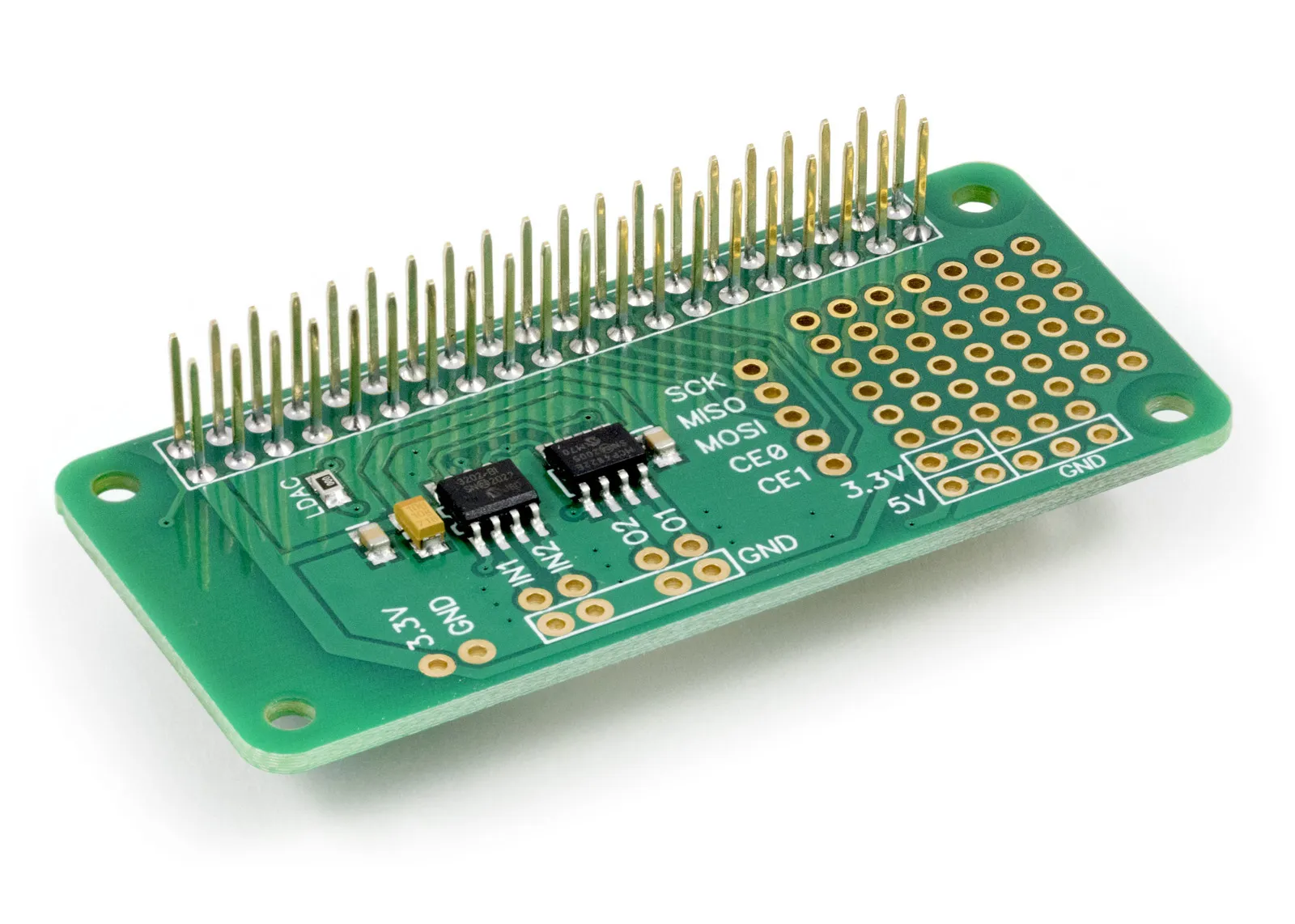
In this tutorial, we will read from the input pins on the ADC DAC Pi and set a voltage on the output pins.
The ADC DAC Pi uses the SPI port, and we will use the py-spidev python module; if you have not installed these already, you can follow our SPI and Python on Raspberry Pi OS tutorial to enable the SPI port on your Raspberry Pi.
We will use the AB Electronics Python library to talk to the ADC DAC Pi. To download the library, visit our Python Library and Demos knowledge base article.
With the Python library installed and the Raspberry Pi configured to use SPI, we can begin building our first project.
Reading from the ADC
The ADC DAC Pi contains two inputs connected to a 12-bit MCP3202 ADC chip and two outputs connected to a 12-bit MCP4822 DAC chip.
We will start by importing the ADCDACPi python library and the time library. The ADCDACPi library communicates with the ADC DAC Pi on your Raspberry Pi. Open a new text document in your favourite text editor and type in the following at the top of the page.
#!/usr/bin/env python
from ADCDACPi import ADCDACPi
import time
Next, we will create an instance of the ADCDACPi class and call it adcdac. The ADCDAC class includes the ability to set the gain for the DAC during initialisation; a value of 1 or 2 is allowed. In this instance, as we are not using the DAC, we will set the gain to 1.
adcdac = ADCDACPi(1)
The MCP3202 ADC uses the Vdd pin as a voltage reference and is connected to the 3.3V pin on the Raspberry Pi. This means the maximum voltage you can measure is the same as that on the 3.3V pin. In an ideal world, the voltage on the 3.3V pin would be precisely 3.3V. Still, this voltage can vary by a small amount due to slight variations in the tolerances of the components used on the Raspberry Pi and depending on what else is connected to the GPIO port. For this reason, you can set the reference voltage using a function called set_adc_refvoltage(). In this tutorial, we will assume that the voltage is precisely 3.3V. Still, when you use the ADC DAC Pi in your project, we recommend using a multimeter to measure the voltage between the 3.3V pin and ground and use that value to increase the accuracy of the ADC DAC Pi.
Add the following code to set the reference voltage for the ADC inputs.
adcdac.set_adc_refvoltage(3.3)
Now we have the ADC DAC Pi set up for reading from the inputs; we can create a while loop which reads a value from IN1 and prints it to the screen. To do this, we will use a function called read_adc_voltage() which reads the value of the specified input and returns it as a number. To read from IN1 you would use read_adc_voltage(1,0), to read from IN2 use read_adc_voltage(2,0).
We will add a 0.5-second delay between each read to make it easier to view the output.
while True:
   print(adcdac.read_adc_voltage(1, 0))
   time.sleep(0.5)
Save the Python script as demo_adcread.py and run it in a terminal using the following command.
python3 demo_adcread.py
If everything works correctly, you should see a list of numbers appear. If you have nothing connected to the inputs, it should return 0.00 or something very close to 0. Connect a voltage source, such as a 1.5V battery, between the IN1 and GND pin and see if the output changes on the screen.
Writing to the DAC
Now we know how to read a voltage from the inputs, and we will try setting a voltage on the output pins. The 12-bit MCP4822 DAC chip contains an internal 2.048V voltage reference, so we can default set the output voltage between 0V and 2.048V. The DAC also includes a gain control, allowing you to choose a gain of 1 or 2. With a gain of 1, the output voltage will be 0V and 2.048V; with a gain of 2, the output will be between 0 and the supply voltage, which in this case is 3.3V.
As with the read voltage tutorial above, we will begin by importing the ADCDACPi python library and the time and RPi.GPIO libraries.
#!/usr/bin/env python
from ADCDACPi import ADCDACPi
import time
import RPi.GPIO as GPIO
The ADC DAC Pi uses GPIO pin 22 to control the LDAC pin on the DAC. For regular operation, this pin needs to be kept low. To do this, we will use the RPi.GPIO library to set pin 22 as output and make it low.
GPIO.setwarnings(False)
GPIO.setmode(GPIO.BOARD)
GPIO.setup(22, GPIO.OUT)
GPIO.output(22, False)
Next, we will create an instance of the ADCDACPi class, call it adcdac and set a DAC gain of 1.
adcdac = ADCDACPi(1)
We will use a function called set_dac_voltage(channel, value) to set the voltage on an output pin. The set_dac_voltage takes two parameters: the output channel and the value to set. We will create a while loop which sets the voltage to 1.5V, waits 0.5 seconds, sets it to 0V and waits another 0.5 seconds. This will produce a 1Hz square wave output on the O1 pin.
while True:
   adcdac.set_dac_voltage(1, 1.5)
   time.sleep(0.5)
   adcdac.set_dac_voltage(1, 0)
   time.sleep(0.5)
Please save the file as demo_dacwrite.py and run it in a terminal using the following command.
python3 demo_dacwrite.py
If you connect a multimeter between the O1 pin and ground, you should see it alternate between 0V and 1.5V; if you have an oscilloscope, you can connect that to the O1 pin and see a square wave on the display. Try changing the sleep values to adjust the speed of the square wave.
When you connect your multimeter or oscilloscope to the ADC DAC Pi, ensure that you do not accidentally short out the O1 or O2 pins to the ground pins. At best, this will cause the Raspberry Pi to reboot; at worst, it could damage the ADC DAC Pi or the Raspberry Pi.
Also useful for your Raspberry Pi project
Temperature & Sensing
1 Wire Pi Plus
Connect dozens of 1-Wire sensors - temperature, iButtons, EEPROMs - via a single GPIO pin. Stacks directly on the 40-pin header.
Analogue I/O
ADC Pi
Read up to 8 analogue inputs - perfect for pairing with your temperature sensors or other analogue-output devices.
All-in-one
Expander Pi
Combines ADC, DAC, 32 GPIO ports and a real-time clock on one board. The most versatile board for complex Raspberry Pi projects.
Chapters
Related Articles
Order these Boards