
RS485 differential pair seems not so differential?
The RS485 Pi is an RS485 interface for the Raspberry Pi
22/01/2019
Posted by:
xlp512
![]()
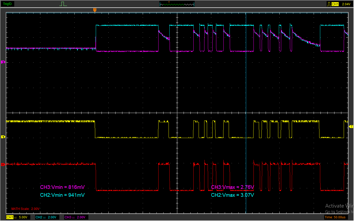
I'm trying to get the RS485-Pi to output a signal that would be compatible with DMX. The UART part is fine, you can see on the picture below Signal 1 (yellow), which is UART out. Then you can see 2 (blue) and 3 (pink), which are the A & B output from RS485. Finally you can see M (red), which is the differential between 2 & 3 (or A & B). And as you can see, the voltage "direction" never changes, it's always negative or 0 (if I would do the math the opposite way, it would be between 0 and X, always positive).
(You cannot see the "2" marker because it's under "3")
 Now let's look at a sample from a commercial DMX USB interface hooked to a Windows running PC:
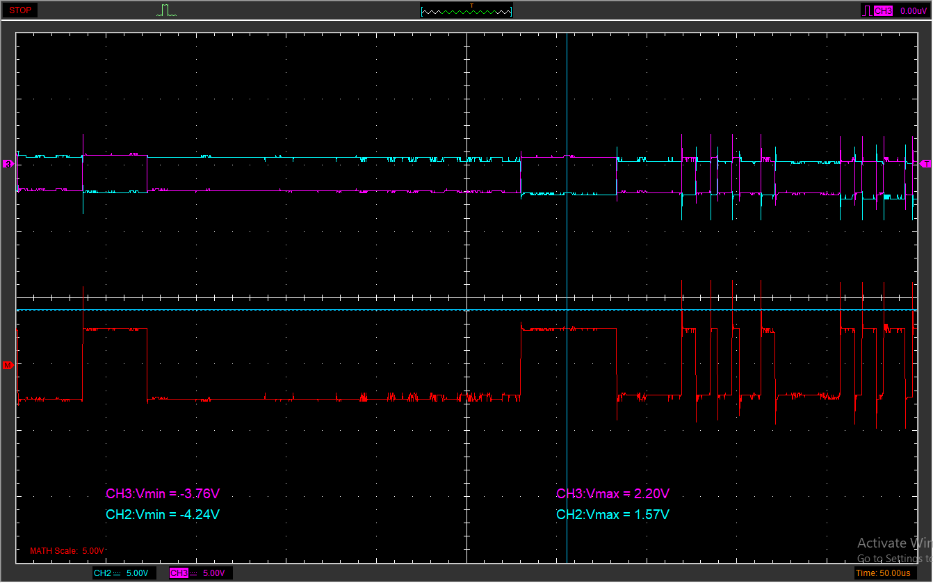 This time, 2 & 3 are clearly opposed, and more importantly, when you look at M, you can see the signal varies between negative and positive.
How do I get such a result with the RS485 board?
(You cannot see the "2" marker because it's under "3")
Now let's look at a sample from a commercial DMX USB interface hooked to a Windows running PC:This time, 2 & 3 are clearly opposed, and more importantly, when you look at M, you can see the signal varies between negative and positive.How do I get such a result with the RS485 board?
22/01/2019
Posted by:
andrew
![]()
Hello
With the RS-485 protocol, the voltage is measured as the difference between the two wires A and B.
If A - B is less than -200mV then that is registered as binary 1. If A - B is more than +200mV then that is registered as binary 0.
The receiver only measures the voltage between the two wires so where they are relative to ground is not important. The specification for RS-485 and EIA-485 allows the voltage to be anywhere between -7V and +12V. The only important part is the difference between the two wires is more than 400mV.
As DMX uses the EIA-485 standard for its physical layer it should be compatible with the RS485 Pi. If the signal output on your commercial DMX USB interface is reversed compared to the RS485 Pi then you should be able to replicate this by swapping the A and B wires around.
22/01/2019
Posted by:
xlp512
![]()
Thank you for your very quick answer! My issue here I guess is that the difference between the 2 wires goes (depending on which you substract to which) between 0 and 2V or -2V and 2V.
In the 2nd screenshot, the difference signal (red) goes approx from -3V to +3V, which complies with what you described (more than +200mV, less than -200mV).
In the first one (output of RS485Pi), the difference never goes above 0V (or never below 0V it plugged in opposite direction), meaning either the <-200mV or the >200mV threshold won't be reached.
Wouldn't that be a problem?
22/01/2019
Posted by:
xlp512
![]()
Forgot to mention: channel 2 & 3 don't have the ground connected, I read that was the way to measure a differential pair
22/01/2019
Posted by:
andrew
![]()
It shouldn't be a problem.
The +200mV and -200mV are relative to the centre point between the two voltages, rather than relative to ground.
In the case of the RS485 Pi, the centre point would be 2.13V so to comply with the RS-485 standard the voltage needs to drop to less than 1.93V and rise to more than 2.33V. As the voltage shifts between 941mV and 3.07V or -1.06V to +1.06V, it should be compatible with any RS-485 device.
26/02/2019
Posted by:
lippo
![]()
Hi guys, I'm struggling with this too. I have been using pyserial's RS485 module with no success. The issue appears to be maintaining the RTS state in transmit. How does the RS485pi switch the RTS state?
Do you have a sample code for python that has been proven to work?
Do you have a sample code for python that has been proven to work?
26/02/2019
Posted by:
andrew
![]()
Hi
The RS485 Pi behaves like a normal serial port when it is plugged into the Raspberry Pi so the RTS pin is not needed on the GPIO port. A MOSFET on the RS485 Pi automatically switches the RS485 transceiver into transmit mode when data is sent down the TXD line.
To use pySerial with the RS485 Pi you can use the serial class. The serial.rs485 class that is included with pySerial will not work properly with the RS485 Pi.
The examples below show a simple program that writes a series of numbers followed by a newline character to a slave RS485 Pi on a second Raspberry Pi. When the slave receives the data it sends it back to the master.
Master Device
Slave Device
The RS485 Pi behaves like a normal serial port when it is plugged into the Raspberry Pi so the RTS pin is not needed on the GPIO port. A MOSFET on the RS485 Pi automatically switches the RS485 transceiver into transmit mode when data is sent down the TXD line.
To use pySerial with the RS485 Pi you can use the serial class. The serial.rs485 class that is included with pySerial will not work properly with the RS485 Pi.
The examples below show a simple program that writes a series of numbers followed by a newline character to a slave RS485 Pi on a second Raspberry Pi. When the slave receives the data it sends it back to the master.
Master Device
#!/usr/bin/env python

import serial


def main():
    '''
    Main Function
    '''
    port = serial.Serial("/dev/ttyAMA0", baudrate=115200)

    # flush buffers
    port.reset_input_buffer()
    port.reset_output_buffer()

    # send a string to the slave
    port.write(b'123456789\n')

    # read the port until a newline character is found
    byteData = port.readline()
    print(str(byteData))

if __name__ == "__main__":
    main()
Slave Device
#!/usr/bin/env python

import serial


def main():
    '''
    Main Function
    '''
    port = serial.Serial("/dev/ttyAMA0", baudrate=115200)

    # flush buffers
    port.reset_input_buffer()
    port.reset_output_buffer()

    # read the port until a newline character is found and
    # write that data back to the port
    while(1):
        byteData = port.readline()
        port.write(byteData)
        print(str(byteData))


if __name__ == "__main__":
    main()
03/03/2021
Posted by:
AsaGong
![]()
Hi....I expect you have built up your own equipment for making interpretation from 232 to 485. There are additionally signal converters for very sensible value that could make the work without issue.
At any rate the 470 Kohm BIAS opposition appears to be very peculiar to me, I get it ought to be 470 ohm. You could likewise attempt without them since network is so little. Kindly advise me on the off chance that it works.
pcb assembly quote
At any rate the 470 Kohm BIAS opposition appears to be very peculiar to me, I get it ought to be 470 ohm. You could likewise attempt without them since network is so little. Kindly advise me on the off chance that it works.
pcb assembly quote
04/03/2021
Posted by:
andrew
![]()
Hi
I have never tried converting RS232 to RS485, we only make boards that convert UART to RS232 and UART to RS485, so I am afraid that I wouldn't know if a 470Kohm bias resistor will work.
It may be worth posting your question on the EEVBlog forum as they have a larger user base who may have experience converting RS232 to 485.
Note: documents in Portable Document Format (PDF) require Adobe Acrobat Reader 5.0 or higher to view.
Download Adobe Acrobat Reader or other PDF reading software for your computer or mobile device.