
Example C code for IO Pi Plus needed
The IO Pi Plus is a 32 channel MCP23017 GPIO expander for the Raspberry Pi
09/02/2020
Posted by:
el Ducko
![]()
from ABE_helpers import ABEHelpers
from ABE_IoPi import IoPi

i2c_helper = ABEHelpers()
i2c_bus = i2c_helper.get_smbus()

# create the two buses
bus1 = IoPi(i2c_bus, 0x20)
bus2 = IoPi(i2c_bus, 0x21)

# set bus 1 to be inputs
bus1.set_port_direction(0, 0xFF)
bus1.set_port_direction(1, 0xFF)

#....etc
which I can't use in C. I haven't had a look at the ABE_helpers file(s) to see if I can "borrow" some code to translate into C. A much better solution would be to find a similar example in C code which can point me in the direction that I need to go.
Can anyone help with a nice, clear example, please? I imagine that it will involve downloading from abelectronicsuk / ABElectronics_C_Libraries
09/02/2020
Posted by:
andrew
![]()
One thing to be aware of when driving relays with the IO Pi Plus is each chip can only supply 20mA per channel and a total of 125mA per bus so you will probably need to use a transistor or Darlington array to drive the relay coils.
We have a design for a 16-channel relay board that works with the IO Pi Plus which we have made available for anyone to download and build themselves, you can find it in our Knowledge Base at: 16 channel relay board. We do not sell the relay board ourselves at the moment but you can use the supplied Gerber files order PCBs from a supplier like JLC PCB.
09/02/2020
Posted by:
el Ducko
![]()
...wish I had known about that relay board when I speced out my hardware. I wound up stacking 8-relay boards and fumbling with building custom 20-wire ribbon cables from the IO Pi Plus cards to connect to 1x10 pin setups on the relay cards. I used pairs of 2x20 socket plugs, plugging the extra row on each with a hot glue gun. Necessity is the mother of... Well, we won't go there. Thanks for the great help. I'll report back, hopefully soon.
09/02/2020
Posted by:
el Ducko
![]()
#include
#include
#include "home/pi/ABElectronics_C_Libraries/IOPi/ABE_IoPi.h"
#include "home/pi/ABElectronics_C_Libraries/I2CSwitch/ABE_I2CSwitch.h"
#include
I modified my$PATH to look in /home/pi/ABElectronics_C_Libraries/IOPi and /home/pi/ABElectronics_C_Libraries/I2CSwitch. I tried building the code with
gcc -Wall -o "%e" "%f" -lwiringPi(I'll need the -lwiringPi switch for my other code.) Unfortunately, I got error messages from the machine trying to link to what may be a library. Message reads: "/tmp/cc7m8eMe.o: In function 'main': undefined reference to IOPi_init"... ditto to "set_port_direction" and the other lines of code. (The usleep() function was no problem. ...makes sense. It's looking specifically for I2C stuff.)
I've probably left out something or installed something wrong. ...any ideas? I think I'm missing links to a library of some sort, but am not sure.
10/02/2020
Posted by:
andrew
![]()
The command I normally use to compile the demo and test program is:
gcc ABE_IoPi.c test.c -o testIt is often easiest to copy the ABE_IoPi.c, ABE_IoPi.h, ABE_I2CSwitch.c and ABE_I2CSwitch.h into the same directory as your program so you can reference them without needing the full path name.
Another alternative is to create a make file that will include all of the libraries and automatically link everything together.
10/02/2020
Posted by:
el Ducko
![]()
IOPi_init(0x20)and other address number attempts with
Failed to write to i2c device for writeso I'm now wondering if I've fouled up the hardware during soldering..(I shouldn't have used an old high-powered soldering gun from the discrete component days.)
The IO Pi Plus 2.1 cards get 5 volts okay, externally supplied (jumper un-soldered).. On one card, the address is set to 0x20; that is, solder pads 0/1/2 are not soldered together for either bus 1 or bus 2. (One thing that I see wrong is that bus 2 pads 0 should be soldered together, right?) Due to poor soldering technique on my part, I've fried a couple of the address solder pads, then tried to remove the solder on the remaining ones, and may have fried something in the process. On my second card, I managed to destroy only one of the solder pads, and have connected the "1" pads to set it up for address 22. Looks like I can solder Bus 2 pads 0 together again, so maybe this card can be salvaged too.
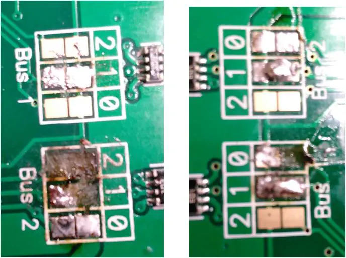
So, what are your thoughts? Have I destroyed the cards and will have to buy two more? Will soldering pads 0 together on both cards' bus 2 fix my problem? (...just tried it. Nope- - no joy.) ...any other thoughts?
10/02/2020
Posted by:
andrew
![]()
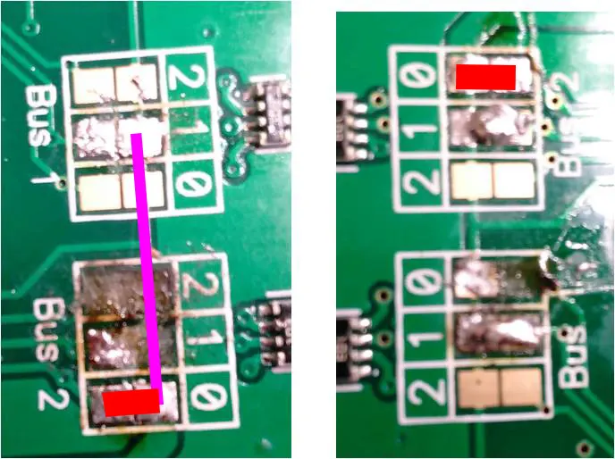
On the first board if you resolder pad 0 on bus 1 and make sure there is no connection between pad 1 on bus 1 that should give you I2C addresses of 0x20 and 0x21.
It looks like you have broken the 5V PCB trace that connects all of the top address pins together so you will need to solder a wire between the top pad 1 on bus 1 and the solder bridge on pad 0 on bus 2. Without this, there will be no 5V supply to the I2C level translator and the board will not appear on the bus. I have marked the image below with a purple line where the wire has to go.
On the second board, the 5V trace looks intact so if you leave bus 1 with pad 1 soldered and solder pad 0 on bus 2 that should give you I2C addresses of 0x22 and 0x23.
You can check if the boards are appearing on the I2C bus by using the command:
sudo i2cdetect -y 1The i2cdetect command scans the I2C bus and returns a list of addresses that have devices.
If you currently only have a high-power soldering iron then it may be worth investing in a smaller iron, or ideally a soldering station with variable temperature control.
We use the Metcal SP200 soldering stations which we found on eBay for around £50. They have replaceable tips that come in a wide range of sizes and temperatures and can be used for soldering devices from large connectors down to 0201 surface mount components.
11/02/2020
Posted by:
el Ducko
![]()
It's time for a confession. As I did the first "smoke test" and powered up the RasPi with the two boards, I wasn't sure how the software worked, but rambled through your AB Electronics website, blundered into i2cdetect, and tried it with no results. I had no idea if i2cdetect told me anything useful, so continued pursuing other software.
I then started checking my wiring, and found that the voltage was 1.5 volts instead of the expected 5 volts. I suspected that the power supply socket I had soldered to one of the boards was installed wrong, removed it, and wired it to the far end of my power bus. This again gave the wrong voltage. I started working my way down the power bus, and discovered to my horror that the wires to the IO Pi Plus boards were reversed. I swapped them and finally got the correct 5 volt power on the power bus. I crossed my fingers, hoping that there was no lasting damage, and started chasing the software angle through this series of posts.
I suspect that I have fried both boards, Am I correct? In that case, I'll need to buy two more boards. I have re-wired the power bus with color-coded wire. (The boards aren't repairable, right?) I worry that I might also have damaged all the other boards, but I can't tell until I get the IO Pi Plus boards running.
So, I've learned a couple of things: (1) use my new low-power soldering gun, and be more careful, especially on the fragile address pads (2) Color-code not just the power bus wiring but all wiring, and double check it with a voltmeter berore connecting it to any of the boards, especially the IO Pi Plus boards (3) don't mount the external power supply socket on either IO Pi Plus board (4) get the software running and check out the IO Pi Plus boards before wiring up the other boards. (5) wire up the boards one-at-a-time, checking as you go.
Thanks for sticking with me through this series of blunders. (Spoiler alert: it's not over yet!)
11/02/2020
Posted by:
andrew
![]()
11/02/2020
Posted by:
el Ducko
![]()
20/02/2020
Posted by:
el Ducko
![]()
sudo i2cdetect -y 1gave the hoped-for responses. The completed installation detects i2c addresses 20, 21, 22, and 23. Thanks very much for your help, Andrew. I've got a fighting chance, now.
My next step will be to hook up the ribbon cables to the relay cards and see if they work okay. Hopefully I didn't fry them like I did the other cards. I'll start a different thread, just in case anyone might benefit from my further adventures. As I mentioned, hooking up 20-wire ribbon cable to two ten-pin relay cards requires taking a few liberties with the cable and pin sockets, plus writing a bit of C code. Cross your fingers!
04/03/2020
Posted by:
el Ducko
![]()
Well, here's that long-awaited post touting success and trumpeting the glories of RasPi and AB Electronics' IO Pi Plus cards. We'll cover the IO Pi Plus 2.1 hardware hookup, how to add relay boards, hardware testing, and a bit of test software.
Installing the AB Electronics Boards
Once my two IO Pi Plus 2.1 32-channel digital expansion HATs for Raspberry Pi were assembled and visually checked out (read about my experiences here, at https://www.abelectronics.co.uk/forums/thread/300/example-c-code-for-io-pi-plus-needed#1175 ) it was time to finish assembly and testing. First step: leave one board with default i2c bus addresses of 20 & 21. Solder jumpers on the second board to set its i2c bus addresses to 22 and 23. Mount the two boards atop the RasPi, using the built-in +5vdc/gnd power and, as Andrew suggested, run
sudo i2cdetect -y 1to make sure the computer “sees” the boards. Mine ran fine, showing all four buses active.
I powered down, then un-soldered both “link” jumpers, and soldered color-coded wires into the plainly-marked +5vdc/gnd pads on each board. I took a razor saw and cut four separate 20-pin sections off an 80-pin dual-row right angle pin header (part number PLD-80P-P5, no brand name). I got lucky, I guess- - local electronic parts distributor Altex had them. One small warning: when soldering these to the pc boards, you need to leave enough space for the socket connectors to firmly seat on these pins. I suggest you take a female 20-pin connector (see below) and slide it onto the pins before you solder the pins to the board. This way, you can guarantee proper clearance.
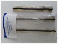

80-pin dual row right angle pin headers female 20-pin connectors
Wire up the external power supply to the two expansion boards, making sure that you connect with the proper polarity. Check it twice. (This is where I went wrong, fried my two expansion boards, and had to buy new ones.) Power up, boot up, run “i2cdetect” again, and verify that everything checks out okay.
Ribbon Cable Connections:
Now, for connecting the relay board hardware to the IO Pi Plus board. As for cables and connectors, I bought 20-wire ribbon cable locally. From Amazon. I bought “Antrader 20 Sets 2.54mm Pitch Connector FC-20 Pin Straight IDC Box Headers Connector Box Headers Female Connector”, 20 of ‘em for $7.00+, pictured above. The thinking, here, is that I have to mate up a 20-wire ribbon cable with two 10-pin relay boards, so I can use two 20-socket box headers separated along the ribbon cable, plug one on the relay board pins with the upper row , and plug the other relay board’s pins with the other header’s lower row. …make sense? …more about that later.
Allow plenty of room between connectors along the ribbon cable for being able to bridge the gap between cards. Just make sure you plug the upper row of one connector on one board and the lower row of the other connector on the other board. After testing, you can block the lower row of sockets on one and the upper on the other with a hot glue gun, but don’t do it until you’ve tested everything and make sure that the cables work. They might not work on the first try if you’re fumble-fingered like me.
For the relay boards, I bought four 8-SPDT relay boards from Robot Shop Inc, “8 Channel 5V Relay Shield Module,” code RB-Suf-19 manufactured by SunFounder, $48 total, and two DPDT 4-relay boards, “ELECTRONICS-SALON Four DPDT Signal Relay Module Board, 5V version” from Amazon for $20.00. The 8-relay boards accept 10-pin sockets, as described above. The DPDT boards accept only bare wire for screw-terminal connections, so you have to separate and strip out the ends of that ribbon cable. I suppose I could have done the same with the 8-relay boards and soldered female sockets on the ends, but that’s a lot of work. At the planning stage, I wanted a clean installation. As a fallback position, I could have gone with soldering female individual sockets, or else wire-wrapped and soldered directly to the pins. Testing will tell! As you will see, fortunately mine worked fine.
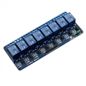
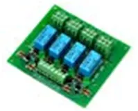
8-relay SPDT Board 4-relay DPDT Board
Now for a complicating factor. Have a look at the pin layout on the Pi HAT, at AB Electronics’ website: https://www.abelectronics.co.uk/p/54/io-pi-plus#specifications where, if you scroll down a bit, you can look at the mechanical drawing which lists the pin-outs. Note that, on a 20-wire ribbon cable, the left two wires are +5VDC and GND, and the right two are interrupts IA and IB. On my 8-relay boards, the 10-pin connections are +5VDC on one side, GND on the other side, and eight input pins marked “IN1” through “IN8” between them. Clearly, if you just slap the things in without making changes, neither of the 10-socket two-row female connectors will line up right! You must do a tiny bit of surgery, as follows.
IO Pi Plus 2.1 Ribbon Cable pin layout (facing card electronics)

IO Pi Plus 2.1 pin layout (facing card edge)
20-pin header layout (side facing IO Pi Plus)

20-pin header layout (side facing Relay cards)
The four wires, +5VDC/GND/IA/IB, clipped between these two headers. On the relay card side, power and ground connections are soldered to the two left wires and the two right wires, and each pair is twisted together as listed below.
Both 20-pin headers layout (facing relay card edge)

20-pin header layout (facing relay card electronics)
Both 8-Relay Boards pin layout (facing card edge)

Both 8-Relay Boards pin layout (facing card electronics)
Note that each row of a female socket carries alternating wires. If you snip the two left wires and the two right wires, that disconnects the one right-hand wire and the one left-hand wire on both of the two sockets. If we then twist the two right-hand wires together and the two left-hand wires together at the end closest to the connections to both relay cards, then apply +5VDC to one set of wire ends and GND to the other set, the power connections for both relay cards are taken care of. Not only that, but Pi-HAT pin 1 goes to one relay card’s pin IN8, Pi-HAT pin 2 goes to the other relay card’s pin IN8, and so on, alternating down the line. Inputs are taken care of, power and ground are taken care of, and all you have to do is figure out which computer code to use to activate whatever desired relay. (There’s software to help with that, later.) Simple, right? “Of course right!”
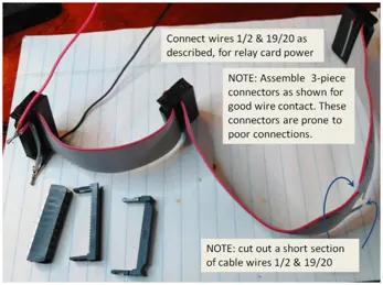
Take care when assembling the ribbon cables and connectors. My first set had poor connectivity because I used only two of the three components pictured below on each connector. See YouTube video YouTube for hints on how to assemble them. Be sure to leave plenty of ribbon cable so you can reach all three connection points. I didn’t leave enough ribbon cable to fold back over the connectors on my first try, and had to discard one and rebuild it.
…almost there, but not so fast! You’ll find that the female header using the back row (farthest from the card edge) collides with the relay board electronics packages when you plug in the front (near card edge) row.. It is important that these connectors seat firmly. To get around this problem, carefully bend the pins on the relay card toward the edge enough that you can seat the 10-sockets of the header firmly. The other socket header will seat firmly on the other relay card without problems.
Alternate Hardware: AB Electronics' 10-Relay PCB
The AB Electronics folks offer a printed circuit board layout for a 16-relay board. See their web page: https://www.abelectronics.co.uk/kb/article/1060/relay-board-for-the-io-pi-plus-2-1 which offers design schematics and PCB files. To quote them, “The 20 pin IDC connector uses the same pin configuration as the IO Pi Plus 2.1 so you can connect the two together using two 20 pin IDC connectors and a ribbon cable. The relay numbers match the pin numbering on the IO Pi Plus bus making it easy to control the relays using our IO Pi software libraries.” You have to get the PCB board made, then buy all the components and assemble them. Given my bad record at soldering and lacking means of getting the board printed, I elected to use commercially available 8-relay boards as described above. I hope you’ll have better success with whatever option you choose.
Software Mods for Testing
One last check, and you’re almost ready to go. Sure, you can “smoke test” by powering it up, but what about turning things off and on? You’ll need software. What’s cool about the relay cards I’ve used is that each relay has a red LED which is activated when the relay turns on. If yours don’t, you’ll need to wire 16 or so LEDs up so you can check easily. Don’t forget the current-limiting 200 W resistors!
The folks at AB Electronics have provided some great code for testing. See their code libraries on Github, or try https://www.abelectronics.co.uk/p/54/io-pi-plus#code for easy access. I modified mine so it would turn on the relays, one at a time, wait for a keystroke, then turn ‘em off. My modified code follows, with apologies to the AB-E folks. First, you’ll need to find, then copy, their files ABE_IoPi.c and ABE_IoPi.h into the same directory as your test code, which I’ve named IO_Pi_test.c which follows below. Then, you may need to make a couple of modifications to ABE_IoPi.c as follows:
If you have a Raspberry Pi Model B revision 0002 or 0003, change line 91 or so as reads
const char *filename = “/dev/i2c-1”
to read
const char *filename = “/dev/i2c-0”
as described on that line in ABE_IoPi.c. This is actually a hardware port. For some reason, port /dev/i2c-0 does not exist in my operating system files, so I didn’t make that change. If you use it and get the error message
Failed to open i2c port for write
chances are that you don’t have that port enabled either. Have a look in /dev to see.
The next change to in ABE_IoPi.c is necessary due to the fact that its write_pin() function requires octal arguments. Scroll down to that subroutine, which begins in my copy at line 242 or so. Change the subroutine to:
void write_pin(char address, char pin, char value)
{	// requires octal input args
	/*
	*	CHANGE:		*	 write to an individual pin 1 - 16
//	*	TO: write to an individual pin 0 - 17 octal
	* @param address - I2C address for the target device
	*	CHANGE:		* 	@param pin - 1 to 16
	*	TO: @param pins 0 to 7, 10 to 17
	* @param value - 0 = logic level low, 1 = logic level high
	*/
//	THE FOLLOWING LINE should be commented out so code will execute correctly
//	pin = pin - 1;
	char cval = 0;
	if (pin < 8) {
		cval = read_byte_data(address, GPIOA);
		cval = updatebyte(cval, pin, value);
		write_byte_data(address, GPIOA, cval);
	} else {
		cval = read_byte_data(address, GPIOB);
		cval = updatebyte(cval, pin - 8, value);
		write_byte_data(address, GPIOB, cval);
	}
}
Assume your code is named IO_Pi_test.c in which case you’ll need to build your code with the following line:
gcc ABE_IoPi.c IO_Pi_test.c -o test
// then run with
./test
Or, if needed,
./test invert
which we’ll talk about in a moment.
Software for Hardware Testing
Here’s the C code, IO_Pi_test.c:
/* Based on AB Electronics "test.c" */
#include
#include
#include
#include
#include
#include
#include
#include "ABE_IoPi.h"
#include "ABE_I2CSwitch.h"
// Andrew at AB Electronics suggests copying the above two files, both
//	the .c file and the .h header file, into the same directory, then
//	using the following build command:
//		gcc ABE_IoPi.c IO_Pi_test.c -o test
// then running with
//		./test

// This program operates relays 0 thru 7, 10 thru 17 octal (two cards
//	of 8 relays each). Note that IO Pi Plus pin numbers are not the same
//	as relay card pin numbers. These are wiring-determined. Use this
//	program to sort out which software pin number is which relay.

// Specify which i2c address to use. Test only one at a time.
//	For two IO PI Plus 2.1 cards, the following four addresses are
//	hard-wired.
#define ADDRESS 0x20	// right (aux) two relay cards 17 - 0
//#define ADDRESS 0x21	// left (main block) two relay cards 17 - 0
//#define ADDRESS 0x22	// fwd/rev relays 7 thru 0 (invert required)
//#define ADDRESS 0x23 // detectors

char on;char off;	// global pin on/off zero or one
char invert;		// global invert switch

void turn_on()	// Turn each relay on, wait, then off and go to next.
{	printf("Turning ON pin-by-pin. Does next pin after  keypress.\n");
	// Print which pin number, output the print line to
	//	stdout (display) buffer, flush it to display on-screen,
	//	write to pin, then wait for  key before turning that pin
	//	off and going to the next pin #. Do pin 017 down to pin 000.
	// LOW level triggers relay on.
	char dummy[1];
	dummy[0]=(char)0;
	// Note that all pin numbers are octal (preceding 0 character).
	if(dummy[0]>00){dummy[0]=00;} // to avoid "not used" warning
	for(char i=017;((i>=000)&&(i<=017));i--)	// for each pin
	{	printf("\rpin %o",i);fflush(stdout);write_pin(ADDRESS,i,on);
		dummy[0]=getchar();write_pin(ADDRESS,i,off);
	} // for()
	printf("ON test complete\n");
}

void turn_em_off()	// Force all relays off. All addresses octal.
{	if(invert) {printf("Initializing (turning all off) with PIN_LOW.\n");}
	else {printf("Initializing (turning all off) with PIN_HIGH.\n");}
	for(char i=017;((i>=000)&&(i<=017));i--)write_pin(ADDRESS,i,off);
}

// Callback handler. Shut down test if CTRL-C signal is detected
void my_handler(int s)
{	printf("Detected CTRL-C signal. Exiting. \n");
	turn_em_off();	// reset to OFF first, though.
	exit(0);
}

int main(int argc, char **argv)
{	// Register callback function for CTRL-C
	signal(SIGINT, my_handler);
	printf("Initializing i2c address.\n");
//	ADDRESS must be defined above
	IOPi_init(ADDRESS); // initialise one of the io pi channels on i2c
	printf("Enabling bus 0 output.  ");
	set_port_direction(ADDRESS, 0, 000); // set bus 0 to be outputs
	printf("Enabling bus 1 output.\n");
	set_port_direction(ADDRESS, 1, 000); // set bus 1 to be outputs
	printf("Press Ctrl-C to exit.\n");
	if(argc>1)
	{invert=1;printf("Inverting pin outputs. OFF means PIN_LOW.\n");}
	else{(invert=0);printf("Standard pin outputs. OFF means PIN_HIGH.\n");}
	if(invert){	on=1;off=0;}
	else {on=0;off=1;}
	turn_em_off();	// initialize
	turn_on();	// run single pass, then exit
	return (0);
}
Pin Signal Inverting
Now for a hardware item. Some relay cards turn their components on in response to a HIGH pin, while others are the opposite. When you power on your equipment, take a multimeter and check that the normally-closed contacts are actually closed and the normally open contacts are open. Now, fire off the test program, running each relay card through its paces one or two times, just to make sure the indicator led lights light or go out when expected.
Now, run it again, checking with the multimeter to see if powering a pin off or on gets the expected relay contact closure. In my case, the DPDT relays were wired up such that turning a pin OFF turned the relay off and caused the led to go out. You’ll need to take this into account when you wire up the relays as well as when you program your computer code. Do you wire the controlled circuit logic inverted, or the controller software? I’d opt for minimizing relay current draw if I were you, which at first glance, means defaulting the pin signals to PIN_LOW.
As luck would have it, the SPDT relay cards defaulted the other way ‘round. PIN_ON means the relay goes to normally closed, i.e. OFF, position. In these cards, logic is inverted and pins should default to PIN_HIGH. In such a case, you should wire and program accordingly. Test this condition with
./test invert
Which in my case will end up with all the LEds turned off, meaning in my case, everything defaults to “normally-whatever,” be it closed or open. I will need to take the “normal” position into consideration when wiring.
NEXT TOPIC: Wiring Design, Relay Logic
05/03/2020
Posted by:
andrew
![]()
18/03/2020
Posted by:
el Ducko
![]()
Part 2 - Design, Electrical Diagram
Please realize that I’ve jumped the gun just a bit on this write-up. The Raspberry Pi hardware and AB Electronics expansion boards were obvious choices for what I wanted to do, so I bought ‘em! Right away, though, I needed some C code. Once my two IO Pi Plus 2.1 32-channel digital expansion HATs for Raspberry Pi were assembled, visually checked out, and fired up, it was time to wire up the relay boards and test them. First, though, I needed a formalized plan. I hope to present it to you here, as long as I don’t wear out my welcome with Andrew & friends. Let’s cover:
Overall Plan
Power Management (Relay Wiring)
RasPi Graphical Interface
Position Detection (hopefully with interrupts)
Smart Power Management System (AI Expert System)
Speed/Power Indication
Motor Regulation
Turnout Position Indication/Operation (manual vs. motorized)
Overall Plan:
For the overall plan, I hope to operate and regulate as much of the model railroad as makes sense, whatever that is. There will be compromises, so don’t expect the complete thing described above to actually come to fruition. I was involved my entire working career with chemical plant automation, though, so I like to think I can scale things to the proper level. (…to be seen!)
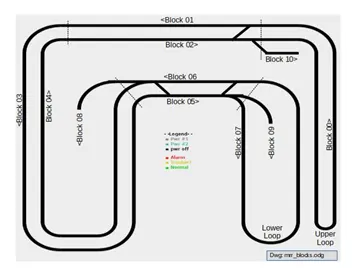
Here’s a layout diagram. There are two power packs, #1 and #2, supplying power to all blocks via two power busses and a common return bus. The current from each of them is switched off or on with a single pole double throw (SPDT) relay. The layout trackage is divided into eight main electrical blocks numbered 00 through 07, each of which needs its own power controls. These controls consist of, for each block, an SPDT relay connection to either one of two power supply packs, an SPDT off/on relay switch, and a double pole, double throw (DPDT) forward/reverse directional control relay. In addition, there are three sidings, numbered 08 through 10. These sidings need only be connected to their adjacent blocks via an SPDT relay, which simplifies wiring considerably. (One rail is soldered to the main block, and the other is connected to its corresponding rail via a single SPDT relay.)
Power Management (Relay Wiring):
Here are some photos of the output relay boards. There are four 8-relay boards and two 4-relay DPDT boards.

The wiring diagrams for a single example of each block, and each siding, are shown below.
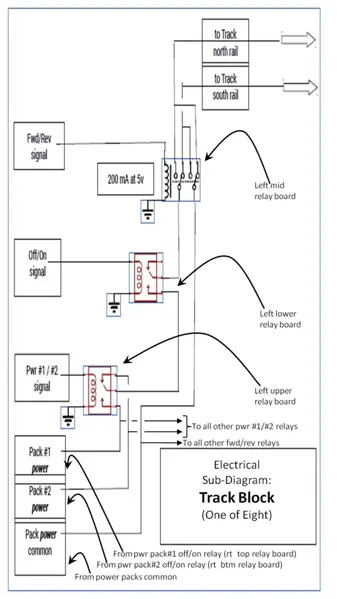
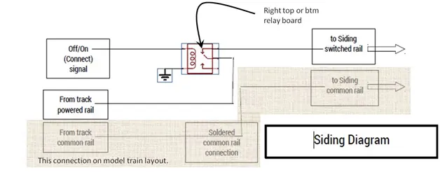
I wired up the power control relays, which is to say, the output relays, as described in my earlier post. Next, it was time to wire up the power side of the relays, the part that hooks to the model railroad. To do so, I needed a block diagram of the layout, plus electrical diagrams of the necessary wiring (see above).
A side note, here: the last fifteen years or so have seen a shift from old-fashioned track electrical blocks operating DC motors to so-called Digi-Trax equipment supplying voltage to the whole layout, with electronic modules in each locomotive which convert the power to the desired DC polarity and voltage as controlled by a digitally encoded signal superimposed on the power. These things cost $200 plus the layout, plus an electronic decoder module ($50 ?) in each locomotive. This gets pricey, fast. Add in the fact that I’m getting older and reluctant to change, and oh yeah, cheap, I decided to stick with what I knew. Yeah, laugh if you will. I’d rather spend my time and money on the computer control end of the hobby, anyway.
So, without further ado, let’s lay out the design and then take a plunge into power system. Here’s a shot of the power management section of the system, with the RasPi on the right. The double-decker SPST relays are center, the DPDT relays are on the left, and a double-decker pair of SPDT relay boards for the main power pack off/on relays and siding power connections are at the rear.
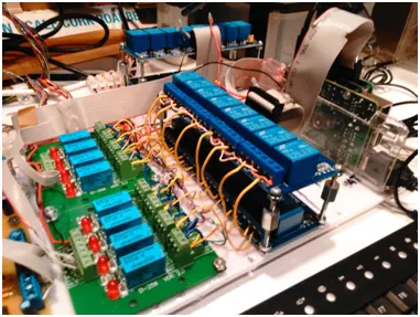
Note the heavy use of color-coded wiring. I can’t stress this enough. I learned the hard way that everything electrical must be triple-checked or you risk burning out components or entire boards. This is especially important in this day of integrated circuits.
You can run through the test program from my previous post, just to make sure that the relays all work via the RasPi. However, to test the power side of the circuitry, you’ll need a bit more elaborate programming. This time, you’ll impose a voltage across one or both power pack supply wiring. This is easily done, at this stage, with wired alligator test clips and a battery holder. Put in a temporary jumper to supply voltage to both power Pack supply leads.
Then, for the testing regimen, you’ll need to, first,
turn on main power pack supply #1 and make sure you can detect the voltage on the power pack buss. Then, turn on #2 and check it.
Next, check the outlet voltage from the block power pack selection relay, which should default to pack #1. Activate it to check that pack #2 can be selected.
Then turn on the block power off/on relay, which defaulted off, and make sure that it passes current.
Then check the voltage on the DPDT forward/reverse relay, to make sure the polarity is correct. Then, activate that relay and check that the polarity reverses.
I’ve mentioned before that the folks at AB Electronics have provided some great code for testing. I’ve cobbled together some code based on theirs that allows you to test the power side of the relays as described above. It’s fairly flexible, allowing you to turn on the relays as described, working your way block-by-block. My modified code follows, with apologies to the AB-E folks. As before, make sure you have copied files ABE_IoPi.c and ABE_IoPi.h into the same directory as your test code, which I’ve named IO_Pi_test2.c which follows below.
Be sure you have made the change in ABE_IoPi.c described in my previous post. Assume your code is named IO_Pi_test2.c in which case you’ll need to build your code with the following line:
gcc ABE_IoPi.c IO_Pi_test2.c -o test2
// then run with
./test2
My approach deals with the fact that we have eight sets of four relays in series, and that testing them one-by-one would involve an inordinate amount of repetitive work. The code I’ve provided works its way through each set of relays, allowing you to logically find short circuits or open circuits. This cuts the amount of work considerably.
Here’s a recent version of the C test code, IO_Pi_test2.c. A few quirks should be mentioned, as discussed in the comments below. You’ll need to do some code modifications to adapt the code to your own needs, of course. I include it here only as an example of what to do for similar applications.
/*	Use this in testing the model railroad wiring	*/
#include
#include
#include
#include
#include
#include
#include
#include "ABE_IoPi.h"
#include "ABE_I2CSwitch.h"

typedef struct block_structure	// pin nmbrs are octal
{	int block_no[11];			//except this one
	char pwr_select_pin[11];
	char block_on_off_pin[11];
	char block_fwd_rev_pin[11];
	char siding_on_off_pin[11];
} block_structure;

block_structure block_relay = // pin nmbrs are octal
{	.block_no ={0,1,2,3,4,5,6,7,8,9,10}, //except this one
	.pwr_select_pin    = {01,03,05,07,011,013,015,017,00,00,00},
	.block_on_off_pin  = {00,02,04,06,010,012,014,016,00,00,00},
	.block_fwd_rev_pin = {07,06,05,04,03,02,01,00,010,010,010},
	.siding_on_off_pin = {017,017,017,017,017,017,017,017,015,014,013}
};

// Specify which i2c addresses to use.
//	For two IO PI Plus 2.1 cards, the following four addresses are hard-wired.
//	They can be char (octal) numbers, although specified as hexadecimal.
//	For two IO PI Plus 2.1 cards, the following four addresses are
//	hard-wired.
char ADDRESS20=0x20;	// right (aux) two relay cards 17 - 0
char ADDRESS21=0x21;	// left (main block) two relay cards 17 - 0
char ADDRESS22=0x22;	// fwd/rev relays 7 thru 0 (invert required)
char ADDRESS23=0x23;	// detectors

char on=0;char off=1;		// global pin on/off zero or one
char on_invert=1;char off_invert=0; // global pin on/off one, zero

// setup for kbd input
char *buffer;
size_t bufsize = 32;
size_t characters;

// SPECIFY BLOCK (RELAYS) TO TEST (pin nmbrs are octal)
char main_pwr_pin=017;			// main pwr pack #1 off/on
char pwr_select_pin; 			// block pwr pack select (#1 or #2)
char block_on_off_pin; 			// block select off/on
char block_fwd_rev_pin;			// block select fwd/rev

void turn_off_all_test_relays()
{//	turn test relays off: PROGRAM END
//		all main power packs off, all block power packs= 1,
//		all blocks on/off = off, all block directions fwd
//		all detectors???
// 	right (aux) two relay cards 17 – 0 (main power packs off/on, sidings)
	write_pin(ADDRESS20,016,off);
	write_pin(ADDRESS20,017,off);
//	left (main blocks) two relay cards 17 – 0 (block pack selection, off/on)
	write_pin(ADDRESS21,pwr_select_pin,off);
	write_pin(ADDRESS21,block_on_off_pin,off);
//	mid left (main blocks) fwd/rev relays 7 thru 0 (fwd/rev direction, invert required)
	write_pin(ADDRESS22,block_fwd_rev_pin,off_invert);
//	far left (main block gaps) detectors SHOULD THE FOLLOWING BE INVERTED???
//	write_pin(ADDRESS23,detect_pin,off_invert);
}

int turn_on_one_relay_set()
{	printf("Turning ON designated relays one at a time.\n Activates next pin after  keypress.\n");
	// Print which pin function, output the print line to
	//	stdout (display) buffer, flush it to display on-screen,
	//	write to pin, then wait for  key before next pin.
	// LOW level triggers SPDT relays on; HIGH triggers DPDT relays on.
	int index;
	char dummy[2];
	dummy[0]=0;if(dummy[0]==0)dummy[0]=0; // so compiler won't complain
	//	// Note that all pin numbers are octal (preceding 0 character).
	// Select block to test
	printf("Enter block number to test (block 0 - 11),\n");
	printf("\r -1 to toggle main power, 99 or c to quit ");
	//	main_pwr_pin defaulted to pwr pack #1 above
	index=000; // default block
	characters = getline(&buffer,&bufsize,stdin);
	index=atoi(buffer);
	if(index==-1)
	{	write_pin(ADDRESS20,main_pwr_pin,off);
		if(main_pwr_pin==017)
		{main_pwr_pin=016;}
		else {main_pwr_pin=017;}
		printf("main power toggled to pin %o\n",main_pwr_pin);
	return(0);
	}
	// 	block_relay.pwr_select_pin[index]; // main pwr pack #1 off/on selected above
	pwr_select_pin=block_relay.pwr_select_pin[index];   // block pwr pack select (#1 or #2)
	block_on_off_pin=block_relay.block_on_off_pin[index];	// block select off/on
	block_fwd_rev_pin=block_relay.block_fwd_rev_pin[index];	// block select fwd/rev
	if((index<0)||(index>11))
	{printf("Exiting %i\n",index);
		return(1);
	}
// turn on power supply main switch
// 	right (aux) two relay cards 17 – 0 (main power packs off/on, sidings)
	write_pin(ADDRESS20,main_pwr_pin,off);
	printf("\rMain pwr ");fflush(stdout);write_pin(ADDRESS20,main_pwr_pin,on);
	dummy[0]=getchar(); // write_pin(ADDRESS,i,off);
// turn on block power pack selection switch
//	left (main blocks) two relay cards 17 – 0 (block pack selection, off/on)
	write_pin(ADDRESS22,pwr_select_pin,off_invert);
	printf("\rPwr select");fflush(stdout);write_pin(ADDRESS21,pwr_select_pin,on);
	dummy[0]=getchar(); // write_pin(ADDRESS,i,off);
// turn on block off/on switch
//	left (main blocks) two relay cards 17 – 0 (block pack selection, off/on)
	write_pin(ADDRESS22,block_on_off_pin,off_invert);
	printf("\rBlock off/on");fflush(stdout);write_pin(ADDRESS21,block_on_off_pin,on);
	dummy[0]=getchar(); // write_pin(ADDRESS,i,off);
// turn on block fwd/rev switch
//	mid left (main blocks) fwd/rev relays 7 thru 0 (fwd/rev direction, invert required)
	write_pin(ADDRESS22,block_fwd_rev_pin,off_invert);
	printf("\rBlock fwd/rev");
		fflush(stdout);write_pin(ADDRESS22,block_fwd_rev_pin,on_invert);
	dummy[0]=getchar(); // write_pin(ADDRESS,i,off);
	printf("ON test complete. Turning relays off.\n");
	turn_off_all_test_relays();
	return(0);
}

void turn_all_relays_off()
{	for(char i=017;((i>=000)&&(i<=017));i--)write_pin(ADDRESS20,i,off);
	for(char i=017;((i>=000)&&(i<=017));i--)write_pin(ADDRESS21,i,off);
	for(char i=007;((i>=000)&&(i<=007));i--)write_pin(ADDRESS22,i,off_invert);
//	for(char i=017;((i>=000)&&(i<=017));i--)write_pin(ADDRESS23,i,off);
}

void map_pins_to_blocks()
{	// initialize pin-block mapping
//#define ADDRESS20 0x20		// right (aux) two relay cards 17 – 0
//	(main power packs off/on, sidings)
	IOPi_init(ADDRESS20); // initialize io pi channel on i2c
	set_port_direction(ADDRESS20, 0, 000); // set bus 0 to be outputs
	set_port_direction(ADDRESS20, 1, 000); // set bus 1 to be outputs
//#define ADDRESS21 0x21		// left (main blocks) two relay cards 17 – 0
//	(block pack selection, off/on)
	IOPi_init(ADDRESS21); // initialize io pi channel on i2c
	set_port_direction(ADDRESS21, 0, 000); // set bus 0 to be outputs
	set_port_direction(ADDRESS21, 1, 000); // set bus 1 to be outputs
//#define ADDRESS22 0x22		// mid left (main blocks) fwd/rev relays 7 thru 0
//	(fwd/rev direction, invert required)
	IOPi_init(ADDRESS22); // initialize io pi channel on i2c
	set_port_direction(ADDRESS22, 0, 000); // set bus 0 to be outputs
	set_port_direction(ADDRESS22, 1, 000); // set bus 1 to be outputs
//#define ADDRESS23 0x23		 // far left (main block gaps) detectors
	IOPi_init(ADDRESS23); // initialize io pi channel on i2c
	set_port_direction(ADDRESS23, 0, 001); // set bus 0 to be INputs
	set_port_direction(ADDRESS23, 1, 001); // set bus 1 to be INputs
}

// Callback handler. Shut down test if CTRL-C signal is detected
void my_handler(int s)
{	printf("\nDetected CTRL-C signal. Exiting. \n");
	turn_all_relays_off();	// reset to OFF.
	exit(0);
}

int main(int argc, char **argv)
{	// Register callback function for CTRL-C
	signal(SIGINT, my_handler);
	// set up stdin for kbd input
    buffer = (char *)malloc(bufsize * sizeof(char));
    if( buffer == NULL)
    {printf("Unable to allocate kbd buffer\n");exit(1);}
	printf("Initializing i2c addresses.\n");
//	ADDRESS is defined in the following
	map_pins_to_blocks();
	printf("Press Ctrl-C to exit.\n");
	turn_all_relays_off();	// initialize
	while(turn_on_one_relay_set()==0);	// run until user signals exit
	return (0);
}
As to adaptations, specifically, the electrical needs of my model railroad dictated that I build in data describing how the relays are grouped, so-called track blocks, for testing purposes. This is done with the "
typedef struct block_structureYou’ll have to completely re-think this data portion of the code, grouping relays so as to fit your needs and expedite testing. To be honest, this code will not be needed once testing is complete, but it sure is handy when you have a network of interacting relays that need to be checked.
As you work your way through testing your equipment, take a multimeter and check that voltages and polarities are correct, one relay at a time. You’ll need to cycle through all blocks 00 through 07, to make sure there are no short circuits or open circuits, then check sidings 08, 09, and 10. My apologies for using decimal numbering for the blocks here, seeing as how the IO Pi equipment selects data bus addresses in hexadecimal but pin numbers in octal. Be very careful as you adapt the code to your needs. If things don’t work the way you expect, check to see that you specified your numbers in the correct notation, 0x1234 (leading 0x) for hexadecimal, 01234 (leading zero) for octal, and nothing special for decimal. Most numerical values are passed as type char, which in the Raspberry Pi Linux world can range from 0 to 255, and are very forgiving (not strictly type-checked, it seems).
NEXT TOPIC: RasPi Graphical Interface
19/03/2020
Posted by:
el Ducko
![]()
19/03/2020
Posted by:
el Ducko
![]()
I'll mention in passing that there are nasty things called "reversing loops" which complicate wiring. Having a loop of track double back on itself forms a short circuit through the rails, unless you take some special precautions (such as rail electrical gaps and a strategically-positioned isolated track power block.) It's simple to handle, but I'll avoid discussing that for the moment. If you are interested, please post a request for details.
As to color coding, I'm fortunate in that, being a pack rat, I've collected wiring over the years. Thirty-some-odd years ago, I cleaned a bunch of 50-conductor color-coded cable out of my wife's new offices during a relocation. It lives on in my model railroading! Things are much easier to troubleshoot when your wiring is color coded.
11/10/2020
Posted by:
el Ducko
![]()
As I left off, I was developing a graphical interface for RasPi and their AB-E expansion boards. It has gone great, and I am able to put up a track diagram, control the power distribution via the AB-E boards and added relay boards by clicking on the diagram, and show status on the graphics, all via C using GTK GLADE code. Outputs: Cool!
I'm now in the portion where I need inputs. I have a pair of very reasonably priced 8-signal PC boards which I bought via Rob Paisley's excellent Canadian website, Circuitous Circuit Index. They're well-designed, and they work! Optical transistors mounted just below the rail ties (that's "sleepers" to you UK guys) turn signals off and on. They output 12-volt signals, in keeping with model railroad tradition, so I've added two opto-isolator boards which convert the output to 5 volt signals for all 16 detection positions.
Here's the problem: the isolator boards' signals drive on-board LEDs, and all the track position detectors work great, but if I plug the 5-volt signals to the AB-E board and set (or not!) the board for input, all but one of the LEDs remain dark, no matter what the signal state. Unplug the input signal header, however, and the LEDs all function as desired.
So, my question: should I insert resistors between voltage converter outputs and the AB-E board inputs? I suspect I'm either over-driving the inputs or there's enough current demand that it pulls more than the 5-volt power supply can produce. Can anyone recommend resistor values? ...or is this the wrong approach?
11/10/2020
Posted by:
andrew
![]()
Check that you have a common ground connection between the optoisolator boards, the 5V power supply and your Raspberry Pi. If the ground is not connected properly you may get a ground loop between another part of the circuit which can cause problems like too much voltage going to the IO Pi inputs.
Try measuring the voltage between the output of the optoisolator and the IO Pi input when they are not connected together. When the IO Pi bus is set as inputs you should measure no more than 5V.
12/10/2020
Posted by:
el Ducko
![]()
I stuck a 10-K resistor in one of the detector circuits. Output of the opto-isolator board with LED lit was 4.82 volts. Connected, the IO Pi side read 0.01 volts. Disconnected, the IO Pi side read zero.
Maybe my code is faulty and I'm not initializing properly. I'm using the following code snippet to initialize the i2C:
IOPi_init(ADDRESS23); // initialize io pi channel on i2c
set_port_direction(ADDRESS23, 0, 001); // set bus 0 to be INputs
set_port_direction(ADDRESS23, 1, 001); // set bus 1 to be INputs
I then loop to read and display all 16 channels with a for() loop containing:
occ_value[i]=read_pin(ADDRESS23,block_relay.occupied_pin_no[i]);
and I turn one of the channels on. I get both the input and the output LEDs lit, and the voltage on the opto-isolator side reads 4.82 volts, but the test program can't see the 0.01 volt signal (which, you have to admit, makes sense because that's pretty low). I've run the test program before, using detector board output which runs 6.1 volts, and the program can see the detector signal. (No LEDs on the detector boards, unfortunately.) I worried that 6.1 volts is too high, though, so I installed those 12-volt to 5 volt opto-isolators.
Hmmm... maybe if I had a smaller-rated resistor? Or, failing that, is 6.1 volts too high for an IO Pi input voltage?
Just for fun, I'm going to try a smaller resistor- - say, 2 k-ohms.
Please advise.
Russ
12/10/2020
Posted by:
andrew
![]()
Your code is only setting the first pin on each port as inputs so all of the other pins will still be outputs.
The third parameter for set_port_direction() needs a single byte number between 0 and 255 or 0x00 and 0xFF. Each pin can be set as an input or output based on the value of the corresponding bit within the byte so for example to set pins 3 and 5 as inputs and the other pins as outputs you would use a value of 0b00010100 in binary, 20 in decimal or 0x14 in hexadecimal. Where you are setting a value of 001 that would set pin 1 as an input and pins 2 to 8 as outputs.
Try changing your code to the following and see if that fixes the problem.
IOPi_init(ADDRESS23); // initialize io pi channel on i2c
set_port_direction(ADDRESS23, 0, 0xFF); // set bus 0 to be INputs
set_port_direction(ADDRESS23, 1, 0xFF); // set bus 1 to be INputs
12/10/2020
Posted by:
el Ducko
![]()
Russ
Note: documents in Portable Document Format (PDF) require Adobe Acrobat Reader 5.0 or higher to view.
Download Adobe Acrobat Reader or other PDF reading software for your computer or mobile device.