
measuring own power supply
The ADC Pi is an Analogue to Digital converter for the Raspberry Pi
26/07/2021
Posted by:
prace@srbpavel.cz
![]()
hi all, as you well know with i2c it is very tricky sometimes.
if i meassure external power source, let's say car battery or simply one 18650 which are not used to power rpi, i get a nice accurate readings
1x 18650 multimeter: 4.127V
adc_pi readings: 4.1167
but since i meassure the battery,which is powering rpi_zero [they have common GND], then i am not able to get accurate reading. this is the setup:
input 12v car battery -> dcdc stepdown --> output 5v --> usb power rpi_zero
then i have a voltage divider with R1 = 51k and R2 = 6k8. this is factor 7.5 so for 12V
U1 = 10.588 V
U2 = 1.41 V
simple schema:
+12 V --> R1 --> [ +A1 ] --> R2 --> -12 V / [ -A1 GND]
all verified with multimeter that math was done correctly. so for 12V betwen +A1 and -A1 i get nice 1.411V with multimeter when rpi is off [i am using same setup to measure 12v and also 5v]
i have to have order like 51k first and 6k8 second so i get +A1 in between both resistors [otherwise the voltage will be not 1.4V but +11V due current travel through i2c bus, so it will kill ADC pi]
running a simple code:
###
from ADCPi import ADCPi
adc = ADCPi(0x68, 0x69, 12) #default i2c settings
adc.set_conversion_mode(1)
samples = 1000
def test(pin):
value = []
for x in range(0, samples):
value.append(adc.read_voltage(pin))
averagevalue = float(sum(value))/max(len(value), 1)
return averagevalue
###
>>>a_result = test(1)
>>> a_result
1.0171278460000053 # this should be close to 1,41V
>>> 12 / a_result
11.797926924517547 #this should be close to 7.5 factor
the same error goes for 5V readings.
when i verify the ADC accuracy and meassure 3.3V from RPI output, i get nice
3.300895234000026V
please, do you have any suggestion on how to improve my circuit for voltage divider to get accurate readings?
thank you, pavel
26/07/2021
Posted by:
andrew
![]()
Hi Pavel
The ADC Pi contains a voltage divider on each input using 10K and 6K8 resistors so to increase the voltage range you can use a single resistor in series with the input to increase the resistance of the 10K resistor.
We have a calculator you can use to find the correct resistor value for your voltage range. You can find it at ADC Pi Input Calculator
For a 12V battery, a 15V voltage range would give a good margin for overvoltage, so a 33.2K resistor connected to the ADC input would increase the voltage range of the ADC to 15.059V. This should be more accurate than adding a second voltage divider in front of the one built into the ADC Pi.
26/07/2021
Posted by:
prace@srbpavel.cz
![]()
hallo andrew, thank you for replay. maybe i wrote it wrongly. will try again:
- i know adc_pi got voltage divider
- i measure 12v and 5V not 15v. but this is not important, what ever i need to measure, i will do the resistor math from voltage input and ouput
- each circuit has it's own voltage divider (one for 5v and second for 12v)
- for 12V i need to use another voltage divider with two resistors, using just one will burn adc_pi,as explained in original post
-also i believe that using another voltage divider will make some offset, but it should not get error like 33%
did you try to measure with adc_pi own power source for rpi like you describe?
thank you,pavel
26/07/2021
Posted by:
prace@srbpavel.cz
![]()
i have give it a try and it looks better. i will need to study this more in deep. thank you , pavel
26/07/2021
Posted by:
andrew
![]()
Hello Pavel
On the ADC Pi, the A- pins are connected to ground so your voltage measurements will be the input voltage relative to ground. If your battery, DC/DC converter and Raspberry Pi all share a common ground you can use a single resistor to drop the voltage on the ADC input through the built-in voltage divider. You will not damage the I2C bus as the built-in voltage divider combined with the external resistor will drop the voltage to a safe range.
The image below shows how you need to connect the 12V battery and 5V wires to the ADC inputs using a resistor on each input.
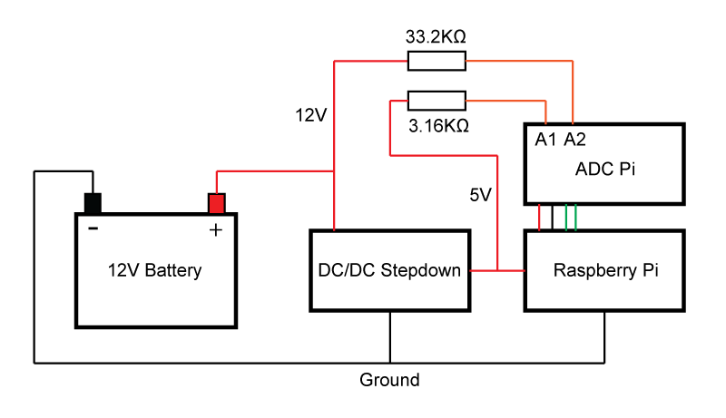
When selecting a resistor for the ADC input you need to use a voltage higher than the expected voltage to allow for a safety margin. A 12V car battery will be higher than 12V when fully charged and can be up to 14.5V when connected to or recently disconnected from a battery charger which is why I suggested a 15V maximum voltage for the ADC input. A 33.2K resistor in series with the 12V battery and the ADC input gives a maximum voltage of 15.059V so you need to multiply the reading from the ADC input by 2.9762 to get the correct voltage.
On the 5V wire, I selected a 3.16K resistor which will give a voltage range of 0 to 6V to allow for any drift in the output from the DC/DC converter. Multiplying the ADC reading by 1.1881 will give you the correct voltage.
On the ADC Pi, the A- pins are connected to ground so your voltage measurements will be the input voltage relative to ground. If your battery, DC/DC converter and Raspberry Pi all share a common ground you can use a single resistor to drop the voltage on the ADC input through the built-in voltage divider. You will not damage the I2C bus as the built-in voltage divider combined with the external resistor will drop the voltage to a safe range.
The image below shows how you need to connect the 12V battery and 5V wires to the ADC inputs using a resistor on each input.
When selecting a resistor for the ADC input you need to use a voltage higher than the expected voltage to allow for a safety margin. A 12V car battery will be higher than 12V when fully charged and can be up to 14.5V when connected to or recently disconnected from a battery charger which is why I suggested a 15V maximum voltage for the ADC input. A 33.2K resistor in series with the 12V battery and the ADC input gives a maximum voltage of 15.059V so you need to multiply the reading from the ADC input by 2.9762 to get the correct voltage.
On the 5V wire, I selected a 3.16K resistor which will give a voltage range of 0 to 6V to allow for any drift in the output from the DC/DC converter. Multiplying the ADC reading by 1.1881 will give you the correct voltage.
Note: documents in Portable Document Format (PDF) require Adobe Acrobat Reader 5.0 or higher to view.
Download Adobe Acrobat Reader or other PDF reading software for your computer or mobile device.