
Voltage Divider on ADC Differential Pi
The ADC Differential Pi is an Analogue to Digital converter for the Raspberry Pi
21/06/2021
Posted by:
jevers99
![]()
Hi,
When using the ADC Differential Pi, do you have any suggestions for reading voltages outside of -2.048 - 2.048? Is it possible to add a voltage divider for examplke?
Thanks,
Jon
When using the ADC Differential Pi, do you have any suggestions for reading voltages outside of -2.048 - 2.048? Is it possible to add a voltage divider for examplke?
Thanks,
Jon
22/06/2021
Posted by:
andrew
![]()
Hi Jon
There are two methods you can use to reduce the voltage level to work on the ADC Differential Pi.
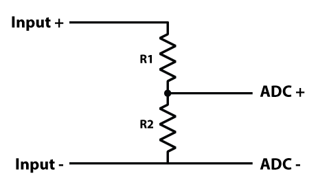
You can use a voltage divider with the positive side going through the R1 resistor before connecting to the ADC + input and the negative connecting directly to the ADC - input. The R2 resistor connects ADC + and ADC -. We have a calculator you can use to get the values for R1 and R2 based on your input voltage. Resistor Voltage Divider Calculator
The second method is to use a fully-differential amplifier. An op-amp circuit is more complicated than a resistor divider but it does have the advantage of a higher impedance between the + and - inputs. Texas Instruments has a good article explaining how to use fully-differential amplifiers at sloa054e
There are two methods you can use to reduce the voltage level to work on the ADC Differential Pi.
You can use a voltage divider with the positive side going through the R1 resistor before connecting to the ADC + input and the negative connecting directly to the ADC - input. The R2 resistor connects ADC + and ADC -. We have a calculator you can use to get the values for R1 and R2 based on your input voltage. Resistor Voltage Divider Calculator
The second method is to use a fully-differential amplifier. An op-amp circuit is more complicated than a resistor divider but it does have the advantage of a higher impedance between the + and - inputs. Texas Instruments has a good article explaining how to use fully-differential amplifiers at sloa054e
09/08/2021
Posted by:
BriggTrim
![]()
Hi.... that appears reasonably agent yes. So the issue is with respect to the differential nature of the voltage perusing I'm attempting to take - the tall end of this perusing must be underneath 5v add up to (and here is 11.1v aprox.). I'm understanding that now. So, would the arrangement here be the swapping the arrange of the resistors (and the ADC examined tests) so that the 11.1v to begin with has got to pass through the bigger resistor? 7pcb
09/08/2021
Posted by:
andrew
![]()
Hi
With an 11.1v input, you would need resistor values of 10K for R1 and 2.2K for R2 which would give you an output voltage of 2.002V.
With this voltage divider setup, you can have a positive or a negative input voltage. A -11.1V input would give you an output voltage of -2.002V.
With an 11.1v input, you would need resistor values of 10K for R1 and 2.2K for R2 which would give you an output voltage of 2.002V.
With this voltage divider setup, you can have a positive or a negative input voltage. A -11.1V input would give you an output voltage of -2.002V.
Note: documents in Portable Document Format (PDF) require Adobe Acrobat Reader 5.0 or higher to view.
Download Adobe Acrobat Reader or other PDF reading software for your computer or mobile device.