
I2C sda data line curious developer
The IO Pi Plus is a 32 channel MCP23017 GPIO expander for the Raspberry Pi
14/03/2017
Posted by:
rs232
![]()
Hi all,I'm debugging I2C ptotocol on IO Pi Plus.Consider as example code: led blinking.The SDA line data that I detected on turning on led event is:[START][ADDR][ACK][0x12][ACK][0x1][ACK][STOP]What means 0x12? It's not enough 0x20 as I2C device address?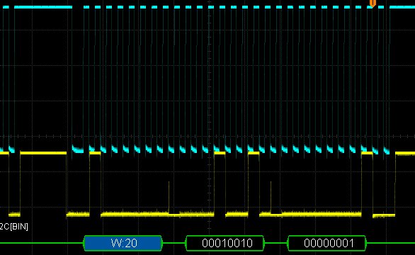 I have anothers two IO Pi plus mounted on my raspberry, but I had no time to investigate the behaviour with different bus.rs232
I have anothers two IO Pi plus mounted on my raspberry, but I had no time to investigate the behaviour with different bus.rs232
14/03/2017
Posted by:
andrew
![]()
Hi
The 0x12 would be the register address for GPIOA which is the first port on the MCP23017 expander chip. When writing to the MCP23017 you normally have to send three bytes, the address of the chip, the register to access and the value to write.
If you look in the python library you can see there is a list of the different registers that are available on the MCP23017 along with their function.
The datasheet for the MCP23017 goes into more detail about how the I2C communication works and what each function does.
Note: documents in Portable Document Format (PDF) require Adobe Acrobat Reader 5.0 or higher to view.
Download Adobe Acrobat Reader or other PDF reading software for your computer or mobile device.