
How to connect ADC Pi and ADC Differential Pi
The ADC Differential Pi is an Analogue to Digital converter for the Raspberry Pi
14/07/2020
Posted by:
jevers99
![]()
Hi,
We're trying to replicate a project we've found on the web - Raspberry Pi current power meter which uses an ADC Pi and an ADC Differential Pi. How do these boards connect to each other, and to external voltages?
Many thanks,
Jon
We're trying to replicate a project we've found on the web - Raspberry Pi current power meter which uses an ADC Pi and an ADC Differential Pi. How do these boards connect to each other, and to external voltages?
Many thanks,
Jon
14/07/2020
Posted by:
andrew
![]()
Hi Jon
If you use the same circuit diagram shown on the website you linked to you would use the ADC Pi for the top ADC with the IN pin connected to one of the input channels and the ADC Differential Pi for the lower ADC with the IN+ connected to + input and the IN- connected to the - input.
The SDA, SCL, VDD and VSS pins shown on the diagram for each ADC would be connected through the Raspberry Pi GPIO header when you stack the ADC boards on top of the Raspberry Pi.
You will need to make sure the Vdd voltage connected to the shunt resistor does not exceed 5V and the voltage across the shunt resistor does not exceed 2.048V.
15/07/2020
Posted by:
jevers99
![]()
Apologies for so many questions. I've seen other boards with IN+ etc marked on them, what is the equivalent on the ADC Differential Pi board?
15/07/2020
Posted by:
andrew
![]()
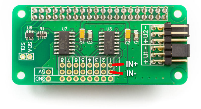
The IN+ pins are the inner row of input pins with a + on the end. The IN- pins are the middle row with a - on the end.
The image below should explain it better.
The image below should explain it better.
15/07/2020
Posted by:
jevers99
![]()
That is fantastic, thank you
Note: documents in Portable Document Format (PDF) require Adobe Acrobat Reader 5.0 or higher to view.
Download Adobe Acrobat Reader or other PDF reading software for your computer or mobile device.