The AB Electronics UK Knowledge Base provides support solutions, tutorials and troubleshooting guides.

Many of our Raspberry Pi development boards are supplied with the connectors unsoldered. We have chosen to sell the boards this way because it makes it easier for the user to modify the board by adding their connectors or fitting it in a lower profile case. To make the soldering of the connectors easier, we have designed an easy-to-use paper assembly jig which you can download and print.

 Print
Print
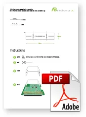
Download and print the PDF from the link below. Set the print size to A4 (210mm x 297mm) and set the printer not to scale to fit the page.
 Cut
Cut 
Cut out the assembly jig along the solid black line. The cut-out jig should be 80mm wide by 18.5mm high.
 Fold
Fold
Fold the jig along each of the broken lines. Each fold should be at a 90-degree angle.
![]()
 Use
Use
Slot the assembly jig onto the printed circuit board on the opposite side of the 40-pin connector. The jig should hold the PCB parallel when the connector is in place, making alignment and soldering easier.
![]()
Watch the assembly video:
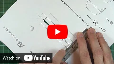
(opens in a new window)
Note: documents in Portable Document Format (PDF) require Adobe Acrobat Reader 5.0 or higher to view, download Adobe Acrobat Reader or other PDF reading software for your computer or mobile device.
Also useful for your Raspberry Pi project
Temperature & Sensing
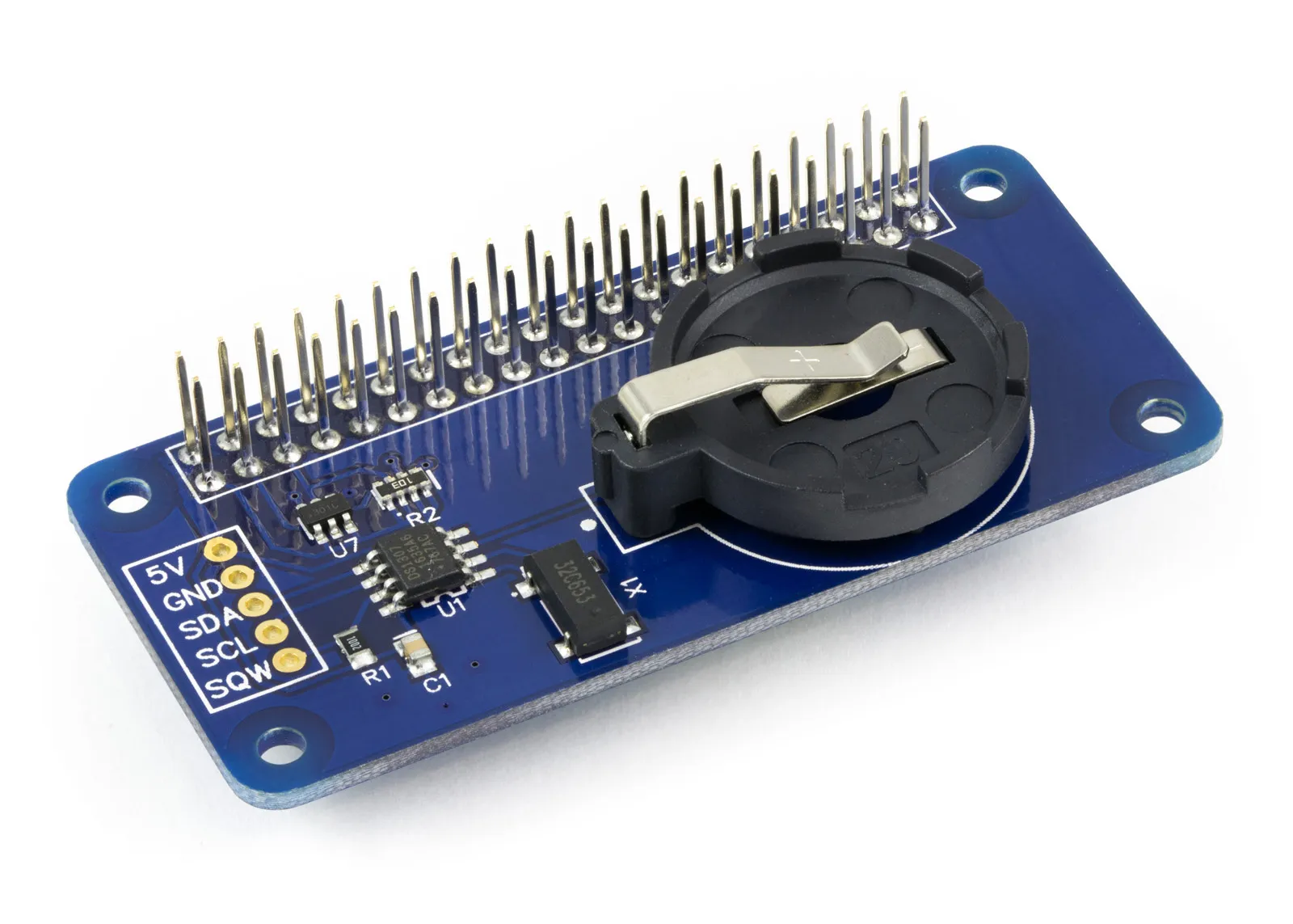
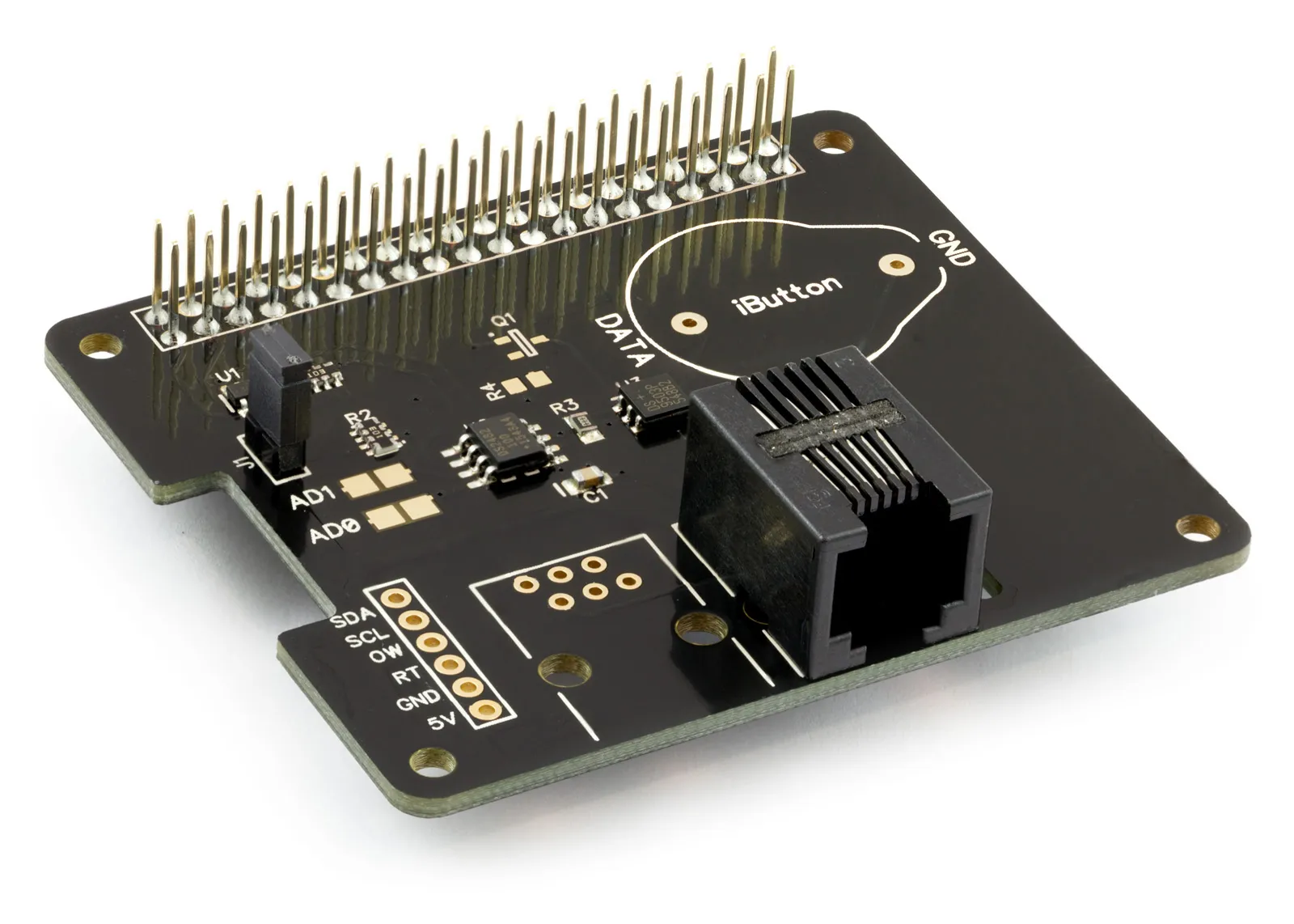
1 Wire Pi Plus
Connect dozens of 1-Wire sensors - temperature, iButtons, EEPROMs - via a single GPIO pin. Stacks directly on the 40-pin header.
Analogue I/O
ADC Pi
Read up to 8 analogue inputs - perfect for pairing with your temperature sensors or other analogue-output devices.
All-in-one
Expander Pi
Combines ADC, DAC, 32 GPIO ports and a real-time clock on one board. The most versatile board for complex Raspberry Pi projects.
Related Articles
- Raspberry Pi GPIO Pins
- PCB Header Assembly Jig
- Samba Setup on Raspberry Pi
- Set a static IP Address on Raspberry Pi OS Trixie
- Set a static IP Address on Raspberry Pi OS Buster
- Set a static IP Address on Raspberry Pi OS Wheezy
- I2C Part 1 - Introducing I2C
- I2C Part 2 - How to Enable I2C on the Raspberry Pi
- I2C Part 3 - I2C tools in Linux
- I2C Part 4 - Programming I2C with Python
- SPI and Python on Raspberry Pi OS
- Using Pythonpath with our Python Libraries
- Connecting Development Boards to the Raspberry Pi 400
Order these Boards
1 Wire Pi Plus
1 Wire interface development board for the Raspberry Pi and Single-Board Computers
£9.59 ex VAT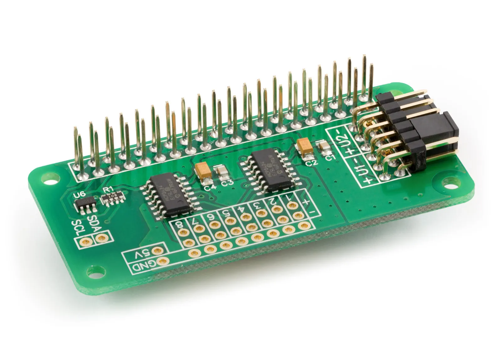
ADC Differential Pi
8 Channel 18-bit Differential Analogue to Digital converter development board for the Raspberry Pi
£13.59 ex VAT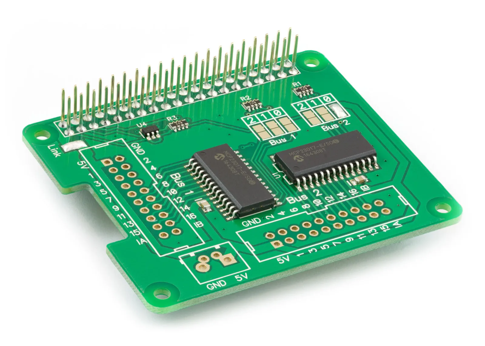
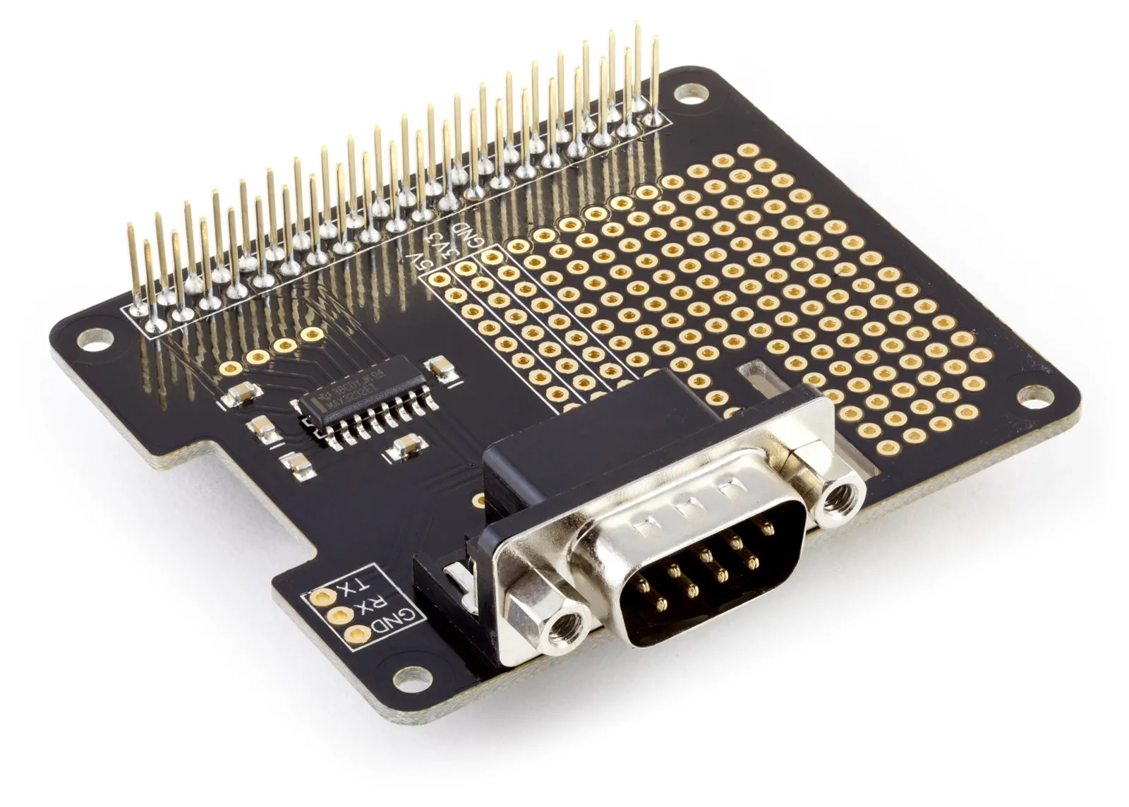
Serial Pi Plus
RS232 Serial Port development board for the Raspberry Pi and Single-Board Computers
£8.79 ex VAT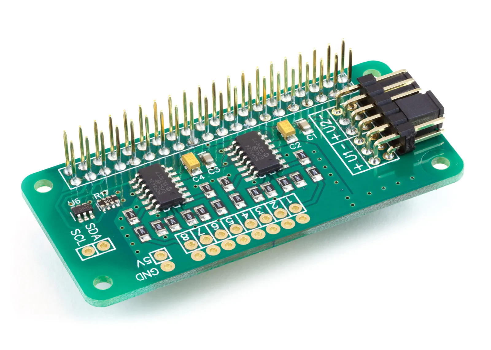
ADC Pi
8 Channel 17-bit Single-Ended Analogue to Digital Converter for the Raspberry Pi and Single-Board Computers
£14.39 ex VAT