The AB Electronics UK Knowledge Base provides support solutions, tutorials and troubleshooting guides.

YOU WILL NEED THIS BOARD
In this tutorial, we will add a button and an LED to the IO Pi Plus and detect when the button has been pressed. You will need your Raspberry Pi, an IO Pi Plus, 1 red LED, 1 200R resistor and a push button.
If you have already completed Tutorial 1, you can jump straight to Stage 1. Otherwise, you will need to complete the steps below.
We will use the AB Electronics Python library to talk to the IO Pi Plus. To download the library, visit our Python Library and Demos knowledge base article.
You must enable i2c on your Raspberry Pi; see our other tutorial on i2c: I2C, SMBus and Raspbian Linux.
The AB Electronics Python library uses another library called python3-smbus; you can install it using apt-get with the following commands.
sudo apt-get update
sudo apt-get install python3-smbus
With the libraries installed and the Raspberry Pi configured to use i2c, we can begin building our first project.
Stage 1 – Connecting the button and the LED
If you haven’t done so, install your IO Pi Plus onto the Raspberry Pi by connecting it to the GPIO header. Make sure your Raspberry Pi is turned off when you do this to minimise the risk of damaging the Raspberry Pi or the IO Pi.
Next, connect the LED and resistor in series between Bus 2 – Pin 8 of the IO Pi Plus and the ground pin, as shown in the picture. Connect your push button between Bus 2 – Pin 1 and the ground pin.
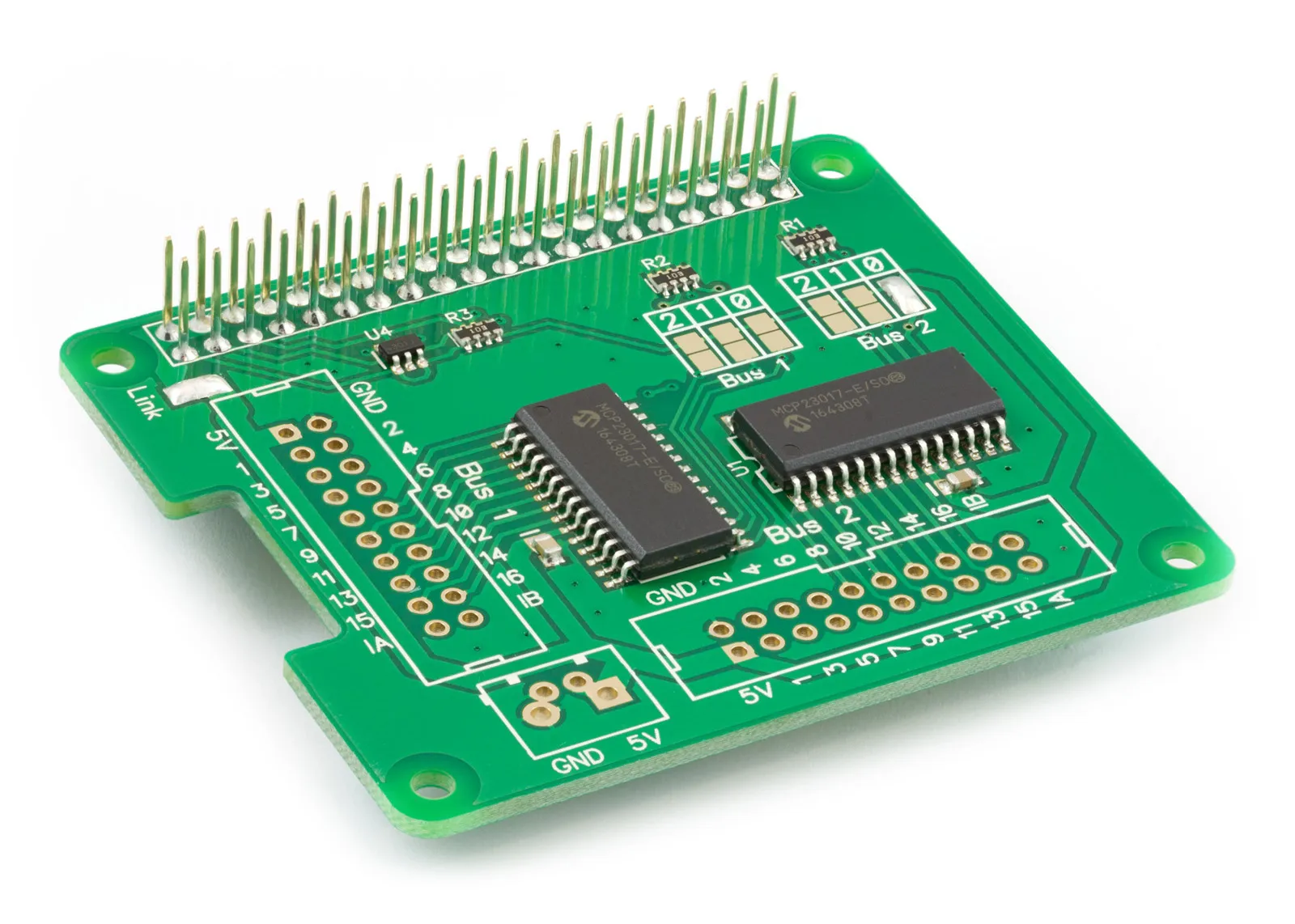
The IO Pi Plus contains two MCP23017 I/O controller chips from Microchip. The MCP23017 is an i2c-based controller having 16 I/O pins, which can be configured individually as inputs or outputs. The two MCP23017 controllers are configured on different I2C addresses so you can control them independently from each other; for more information on setting the I2C addresses, see the IO Pi Plus product page.
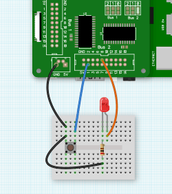
The maximum current you can draw from any of the pins on the MCP23017 is 25mA, so using the 200R resistor in series with the LED limits the current to a safe level.
We will start by creating a new Python program file called tutorial2.py for this tutorial. You can use your favourite text editor to write the program. You can find a complete example of tutorial2.py in the ABElectronics_Python_Libraries/IOPi/ folder.
At the top of your program, you will need to import the IOPI library and time library.
#!/usr/bin/env python
from IOPi import IOPi
import time
The IOPI library is used for all communication with your IO Pi Plus; it gives you control over almost everything that can be done with the MCP23017 controller.
As we will only be using one of the MCP23017 controllers, we will create an instance of the IOPI class and call it bus. To use both controller chips, you must create two separate instances of the IOPI class with the I2C addresses for each chip.
bus = IOPi(0x21)
0x21 is the I2C address for the controller chip on bus 2; if you have changed the address selection jumpers on your IO Pi Plus, you must change this number to match the new address.
With our new instance of the IOPI class, we can access all available methods for controlling the IO Pi Plus. Let’s begin by setting pin 1 as an input and pin 8 as an output.
bus.set_pin_direction(1, 1)
bus.set_pin_direction(8, 0)
The set_pin-direction method allows us to individually set the direction of each of the 16 pins on the bus.
set_pin-direction takes two variables; the first is the pin you want to control, pins 1 to 16. The second variable is the command byte for setting the pin direction. Setting a pin to 0 makes it an output, while setting it to 1 makes it an input; remember, 0 = out, 1 = in.
Next, we will turn off pin 8 with the write_pin method.
bus.write_pin(8,0)
As with setPinDirection, write_pin takes two variables: the first is the pin to write to, and the second is the value to send to the port. Sending a 0 turns a pin off, while sending a 1 turns the pin on.
The IO Pi Plus is now set up to turn our LED on and off; next, we must set up the button.
There are a couple of ways to connect a button to the IO Pi Plus; you could connect it between an input pin and 5V or an input pin and ground.
Using the 5V method, you will need a pull-down resistor between the input pin and ground. The inputs on the IO Pi Plus contain a tiny amount of capacitance. When you release the button, even though the 5V is no longer connected, a small charge will remain on the pin, enough for the IO Pi Plus to get confused and not know if it should read the pin as on or off. A pull-down resistor removes the remaining charge by allowing it to flow to ground.
The second method we use here is connecting the button between the input pin and ground. Usually, you would need to use a resistor to act as a pull-up so there is a constant 5V supply to the pin when the button is not pressed. Still, luckily, the IO Pi Plus comes with pull-up resistors inside the chip, which you can enable using the following method.
bus.set_pin_pullup(1, 1)
set_pin_pullup enables or disables the internal 100K pull-up resistors on any input pins. The method takes two variables: the first is the pin you want to control, and the second tells it to enable or disable the pull-up. 1 enables the pull-up, while 0 disables it.
One downside of using a pull-up resistor rather than a pull-down is that when the button is not pressed, the IO Pi Plus will always read the pin as active so that it would read 1 or on when the button is off and 0 or on when the button is pressed, which is backwards to what you would typically expect from a switch. This can be easily fixed with another useful method called invert_pin.
bus.invert_pin(1, 1)
invert_pin does precisely what it says; it inverts the reading on an input pin, so 1 becomes 0 and 0 becomes 1, and everything looks how it should again. The method uses the same parameters as setPinPullup, with the first parameter setting the pin to invert and the second enabling or disabling the inverter with 1 or 0.
We now have an LED output and a button for input; we can add a while loop where the button-checking code will sit.
while True:
We need to check with an IF statement to see if the button is pressed; this can be done with the read_pin method.
if bus.read_pin(1) == 1:
read_pin takes one variable, the number of the pin to read. It returns a 1 or 0, showing the current state of the pin.
If the button is pressed, we want to show it somehow, so let’s print a message to the screen and light the LED for 2 seconds.
    print 'button pressed' # print a message to the screen
    bus.write_pin(8, 1)
    time.sleep(2)
If you run the program now, you will see the LED lights when you press the button, but it will stay on after the button is released and not go out even after the program has ended. We need to add an ELSE statement to the end of the IF statement so it turns the LED off after 2 seconds if the button is no longer pressed.
else:
    bus.write_pin(8, 0)
This is all the code we need to make the program work; it should now look like this.
from IOPi import IOPi
import time

bus = IOPi(0x20)
bus.set_pin_direction(1, 1)  # set pin 1 as an input
bus.set_pin_direction(8, 0)  # set pin 8 as an output
bus.write_pin(8, 0)  # turn off pin 8
bus.set_pin_pullup(1, 1)  # enable the internal pull-up resistor on pin 1
bus.invert_pin(1, 1)  # invert pin 1 so a button press will register as 1

while True:
    if bus.read_pin(1) == 1:  # check to see if the button is pressed
        print 'button pressed'  # print a message to the screen
        bus.write_pin(8, 1)  # turn on the led on pin 8
        time.sleep(2)  # wait 2 seconds
    else:
        bus.write_pin(8, 0)  # turn off the led on pin 8
Save your program and run it in a command terminal using
python3 tutorial2.py
If everything goes as planned, your LED should turn on for 2 seconds every time you press the button.
(images created with Fritzing)
Also useful for your Raspberry Pi project
Temperature & Sensing
1 Wire Pi Plus
Connect dozens of 1-Wire sensors - temperature, iButtons, EEPROMs - via a single GPIO pin. Stacks directly on the 40-pin header.
Analogue I/O
ADC Pi
Read up to 8 analogue inputs - perfect for pairing with your temperature sensors or other analogue-output devices.
All-in-one
Expander Pi
Combines ADC, DAC, 32 GPIO ports and a real-time clock on one board. The most versatile board for complex Raspberry Pi projects.
Related Articles
- IO Pi Plus FAQ
- IO Pi Plus Tutorial 1 - The Blinking LED
- IO Pi Plus Tutorial 2 - Push the Button
- IO Pi Plus Tutorial 3 - Introducing Interrupts
- IO Pi Plus Tutorial 4 - More Interrupts
- IO Pi Plus Tutorial - MQTT Reading the Ports
- IO Pi Plus with Raspberry Pi Pico
- IO Pi Plus Tutorial - MQTT Control
- Driving Relays or Higher Loads with the IO Pi Plus
- Relay Board for the IO Pi Plus 2.1
- 16 Channel Opto-Isolated Input Board