The AB Electronics UK Knowledge Base provides support solutions, tutorials and troubleshooting guides.

YOU WILL NEED THIS BOARD
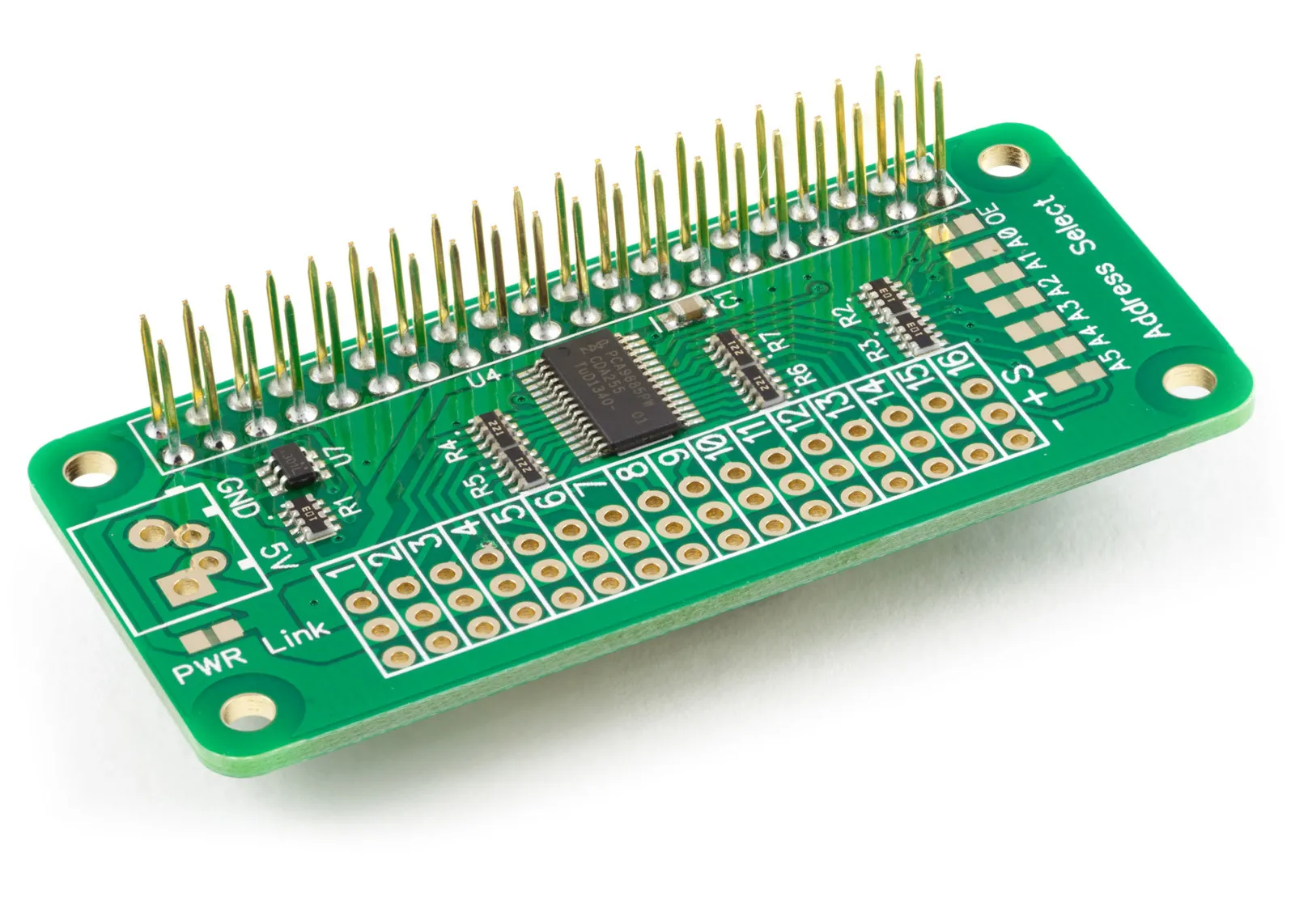
Servo PWM Pi
16 Channel 12-bit PWM and Servo Driver with I2C interface using PCA9685 for driving LEDs and RC servos
£9.49 ex VAT
The Servo PWM Pi Zero and Servo Pi are 16-channel, 12-bit PWM controllers for the Raspberry Pi, suitable for driving LEDs and radio control servos. The boards are based around the PCA9685 PWM I2C LED controller from NXT and can drive each of the 16 outputs with a 12-bit (4096 steps) duty cycle. This tutorial will use the Servo PWM Pi Zero and our Servo Pi Python library.
What is PWM?
PWM or Pulse Width Modulation generates a digital signal where the on and off periods can be set in the controller. Pulse Width Modulation has many uses, but the most common are controlling motors and generating the equivalent of an analogue voltage using digital means.
The duration of the on time in a PWM signal is called the pulse width, and the percentage of the on time compared to the off time is called the duty cycle. By altering the duty cycle, you can change the portion of the time the signal spends at 5V or 0V. If you connect an LED to one of the PWM outputs, you can vary the brightness of the LED by adjusting the duty cycle. This happens because the LED receives the same amount of energy as it would with a lower analogue voltage, so a duty cycle of 20% on a 5V signal would be the same as supplying the LED with a continuous 1V from an analogue power supply. Generating an analogue voltage from digital pulses has various uses within electronic circuits. It is the method used to create a stable voltage in modern switch-mode power supplies like the ones found in computers and mobile phone chargers.
The graphic below shows five different duty cycles for a PWM signal from 0% to 100%.

Each of the green vertical lines in the graph represents a clock cycle. The frequency of the clock cycles on the Servo PWM Pi Zero is programmable and can be set between 40Hz to 1000Hz. When driving LEDs, you want to pick a frequency high enough for the human eye not to notice the flickering. Anything above 200Hz should be suitable.
Using the Servo PWM Pi Zero with Python
We will use the AB Electronics UK Python library to talk to the Servo PWM Pi Zero. To download the library, visit our Python Library and Demos knowledge base article.
You must enable i2c on your Raspberry Pi; see our other tutorial on i2c: I2C, SMBus and Raspbian Linux.
The AB Electronics UK Python library uses two libraries called python3-smbus and RPi.GPIO, you can install both libraries using apt-get with the following commands.
sudo apt-get update
sudo apt-get install python3-smbus python3-rpi.gpio
With the libraries installed and the Raspberry Pi configured to use i2c, we can begin.
Generating a PWM signal
If you haven’t done so, install your Servo PWM Pi Zero onto your Raspberry Pi by connecting it to the GPIO header.
Open your favourite text editor and create a new file called tutorial1.py
The first thing we need to do is import the PWM class from the ServoPi module.
from ServoPi import PWM
If you have installed the Python library onto your Raspberry Pi using the setup.py file or PIP, your program should import the ServoPi module from the system path. Otherwise, you must copy ServoPi.py into the same folder as tutorial1.py.
To access the Servo PWM Pi Zero, you will create an instance of the PWM class and call it pwm with the I2C address for the board. The I2C address can be changed using the solder bridges on the board, but by default, it is 0x40.
pwm = PWM(0x40)
With the pwm object created, we will set the frequency for the output pulses. We do this with the set_pwm_freq() function. The frequency can be any value between 40Hz and 1KHz, so for this tutorial, we will use the upper limit and set the value as 1000Hz or 1Khz.
pwm.set_pwm_freq(1000)
The Servo PWM Pi Zero includes an output enable function which allows you to turn all the PWM channels on or off at the same time using GPIO4 or pin 7 of your Raspberry Pi GPIO header. This function is helpful if you have several devices connected to your board that you want to switch on or off simultaneously.
If you have enabled the output enable function by bridging the OE jumper, you need to call output_enable() to turn the PWM channels on. You can turn them off again by using output_disable().
output_enable()
Now we have set the frequency and enabled the outputs; we can create a pulse on the outputs using the set_pwm() function.
set_pwm(channel, on, off) takes three parameters: channel, on time and off time.
The channel parameter sets the channel you want to update. This parameter takes a number between 1 and 16.
The on time and off time parameters are 12-bit values, meaning they take a number between 0 and 4095. The on parameter is the time when you want the pulse to turn on, and the off position is the time when you want it to turn off, plus the on time.
Each clock cycle is divided up into 4096 segments. We set the clock frequency for this project at 1Khz, meaning each clock cycle is 1 millisecond long. 1ms divided by 4096 equals approximately 0.000,000,244 seconds or 244ns so each pulse can be between 244ns and 1ms.
If you wanted a pulse length of 100 μs and a 10% duty cycle of 1ms, you would use the calculation: 0.0001 / 0.000000244 = 409.83 or rounded up to 410.
The following formula can be used when calculating the value for the on and off parameters.
x = 4096pf
p = length of the pulse in seconds
f = frequency of the clock in hertz
If you want to create a pulse on channel 1 with a length of 410 starting at the beginning of the clock cycle, you would set the channel to 1, use an on time of 0 and an off time of 410.
pwm.set_pwm(1, 0, 410)
Save the Python program and run it with the following command.
python tutorial1.py
You should see something like the following image if you have an oscilloscope or logic analyser connected to channel 1 on your Servo PWM Pi Zero.

By changing the ‘on’ parameter, you can change when the pulse begins during each clock cycle. Add the following lines of code to your program.
pwm.set_pwm(2, 410, 820)
pwm.set_pwm(3, 820, 1230)
pwm.set_pwm(4, 1230, 1640)
Save the program and rerun it. You should see something like the following image if you have a four-channel oscilloscope or logic analyser connected to channels 1 to 4.

Notice how the pulse on channel 2 begins as the pulse on channel 1 ends, and so on for channels 3 and 4. This is because we changed the on time for each channel to match the off time for the previous channel.
On channel 2, the on-time was set to 410, which is 100μs after the start of the clock cycle. As we wanted the pulse length to be 100μs, we had to add 410 to the off time to make it 810. This was repeated for channels 3 and 4. The off time should always equal the on time plus the pulse duration. It should also never be more than 4095.
So why would you set the pulses to start at different times?
Let’s say you have a circuit with 10 LEDs connected to 10 channels on the Servo PWM Pi Zero. Each LED draws 20mA when switched on, and you want to light the LEDs with a 10% duty cycle. During the on period of the pulse, each LED will draw 20mA, so if all the pulses start at the same point in the duty cycle, you will have 10 LEDs all drawing power at the same time, with 200mA being used in total.
If we offset the pulses so that channel 2 starts 10% into the cycle, and channel 3 starts 20% in, each LED will still be turning on for the same amount of time, but only one LED will ever be powered at the same time so the total current being drawn on your circuit will only be 20mA. As well as reducing the power supply size you need to light the LEDs, you can minimise current surges by staggering the pulses.
Please read the component datasheet for a more detailed explanation of the PCA9685 PWM controller used on the Servo PWM Pi Zero.
Note: documents in Portable Document Format (PDF) require Adobe Acrobat Reader 5.0 or higher to view, download Adobe Acrobat Reader or other PDF reading software for your computer or mobile device.
Also useful for your Raspberry Pi project
Temperature & Sensing
1 Wire Pi Plus
Connect dozens of 1-Wire sensors - temperature, iButtons, EEPROMs - via a single GPIO pin. Stacks directly on the 40-pin header.
Analogue I/O
ADC Pi
Read up to 8 analogue inputs - perfect for pairing with your temperature sensors or other analogue-output devices.
All-in-one
Expander Pi
Combines ADC, DAC, 32 GPIO ports and a real-time clock on one board. The most versatile board for complex Raspberry Pi projects.
Related Articles
Order these Boards
Servo PWM Pi
16 Channel 12-bit PWM and Servo Driver with I2C interface using PCA9685 for driving LEDs and RC servos
£9.49 ex VAT