The AB Electronics UK Knowledge Base provides support solutions, tutorials and troubleshooting guides.

-
Raspberry Pi Tutorials
- PCB Header Assembly Jig
- Raspberry Pi GPIO Pins
- Samba Setup on Raspberry Pi
- Set a static IP Address on Raspberry Pi OS Trixie
- Set a static IP Address on Raspberry Pi OS Buster
- Set a static IP Address on Raspberry Pi OS Wheezy
- I2C Part 1 - Introducing I2C
- I2C Part 2 - How to Enable I2C on the Raspberry Pi
- I2C Part 3 - I2C tools in Linux
- I2C Part 4 - Programming I2C with Python
- SPI and Python on Raspberry Pi OS
- Using Pythonpath with our Python Libraries
- Connecting Development Boards to the Raspberry Pi 400
- General
- Code & Languages
- Raspberry Pi Pico Tutorials
- 1 Wire Pi Tutorials
- ADC Pi Tutorials
- ADC DAC Pi Zero Tutorials
- ADC Differential Pi Tutorials
- Expander Pi Tutorials
-
IO Pi Plus Tutorials
- IO Pi Plus FAQ
- IO Pi Plus Tutorial 1 - The Blinking LED
- IO Pi Plus Tutorial 2 - Push the Button
- IO Pi Plus Tutorial 3 - Introducing Interrupts
- IO Pi Plus Tutorial 4 - More Interrupts
- IO Pi Plus Tutorial - MQTT Reading the Ports
- IO Pi Plus with Raspberry Pi Pico
- IO Pi Plus Tutorial - MQTT Control
- Driving Relays or Higher Loads with the IO Pi Plus
- 16 Channel Opto-Isolated Input Board
- Relay Board for the IO Pi Plus 2.1
- IO Zero 32 Tutorials
- RTC Pi Tutorials
- Serial Pi
- Servo PWM Pi Tutorials
-
Home Assistant
- Using 1 Wire with Home Assistant and the Raspberry Pi OS
- Using I2C Devices on the Raspberry Pi with Home Assistant
- Using the ADC Differential Pi with Home Assistant on the Raspberry Pi
- Using the ADC Pi with Home Assistant on the Raspberry Pi
- Using the IO Pi Plus with Home Assistant on the Raspberry Pi
-
Legacy Products
- ADC DAC Pi (Discontinued)
- ADC Pi (Discontinued)
- Buffer Pi - Legacy Product
- Com Pi (Discontinued)
- Delta-Sigma Pi (Discontinued)
- Expander Pi (Discontinued)
- IO Pi (Discontinued)
- IO Pi Plus 1.0 (Discontinued)
- IO Pi Zero (Discontinued)
- Logic Level Converter (Discontinued)
- RTC Alarm Pi (Discontinued)
- RTC Pi (Discontinued)
- Serial Pi (Discontinued)
- 1 Wire Pi (Discontinued)
- 1 Wire Pi Plus 1.0 (Discontinued)
- Other Supported Platforms
I2C and SMBus on the Tinker Board
Configuring I2C and SMBus with Python on the Asus Tinker Board
The Asus Tinker Board contains two I²C buses on the 40-pin GPIO header named I2C1 and I2C4, as shown in the image below. I2C1 uses pin 3 for SDA and 5 for SCL. I2C4 uses pin 27 for SDA and 28 for SCL.
This page details how to set up I²C support for the I2C1 bus, which is used by most Raspberry Pi compatible hats and development boards, including those from AB Electronics UK.
Step 1: Download the latest TinkerOS Debian image for your Tinker Board and burn it to your SD Card following the instructions on eLinux
Step 2: Next, you need to update your Tinker Board to ensure all the latest packages are installed:
sudo apt-get update
sudo apt-get upgrade
Step 3 a: Once you have updated your Tinker Board, run the following command to install the Python smbus and dev libraries and the i2c-tools packages:
sudo apt-get install python3-smbus python3-dev i2c-tools
Step 4: Edit the /boot/config.txt file using nano or your preferred text editor:
sudo nano /boot/config.txt
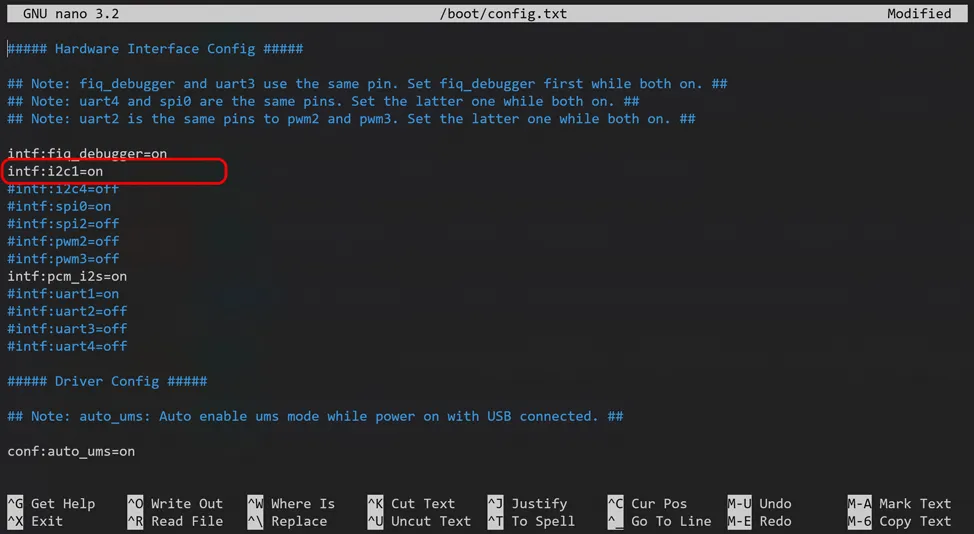
Uncomment the line "intf:i2c1=on" as shown in the screenshot below, and save the file. To use the I2C4 bus, uncomment the "intf:i2c4=on" line changing "off" to "on".
Step 5: To avoid needing to run the I²C tools at root, add the 'linaro' user to the "i2c" group:
sudo adduser linaro i2c
Step 6: Next, reboot the Tinker Board:
sudo reboot
When your Tinker Board has rebooted, you will now have I²C and SMBus Python support.
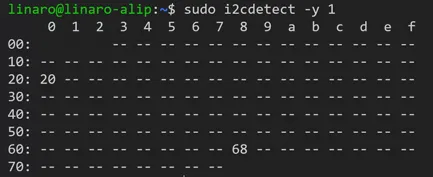
You can find available I²C devices using the following command.
sudo i2cdetect -y 1
A grid of I²C addresses will be displayed with available devices shown by their address number.
To learn more about I²C and how to use it, read our tutorial series Introducing I2C.
Table of Contents
Related Products
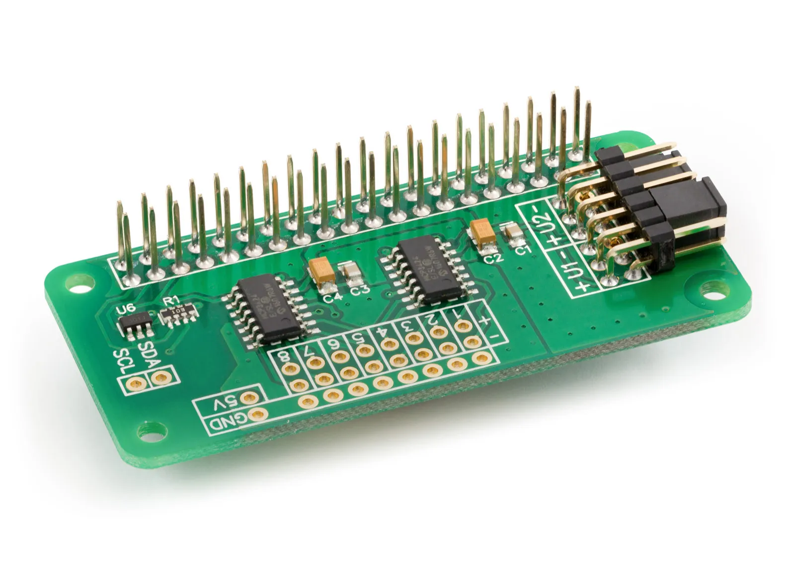
ADC Differential Pi
8 Channel 18-bit Differential Analogue to Digital converter development board for the Raspberry Pi
£16.99 ex VAT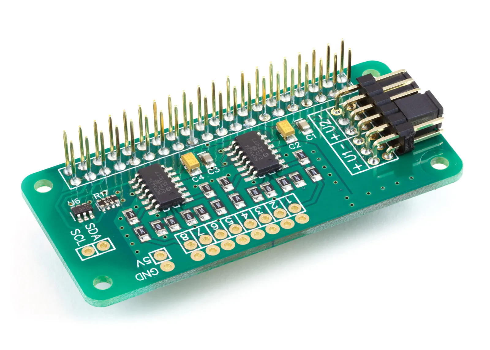
ADC Pi
8 Channel 17-bit Single-Ended Analogue to Digital Converter for the Raspberry Pi
£17.99 ex VAT