In this tutorial, we will add a button and an LED to the IO Zero 32 and detect when the button has been pressed. You will need your Raspberry Pi, an IO Zero 32, one red LED, one 500R resistor, one 100K resistor and a push button.
If you have already completed Tutorial 1, you can jump straight to stage 1. Otherwise, you will need to complete the steps below.
We will use the AB Electronics UK Python library to talk to the IO Zero 32. To download the library, visit our Python Library and Demos knowledge base article.
You must enable I2C on your Raspberry Pi; see our other tutorial, I2C Part 2 - Enabling I²C on the Raspberry Pi.
The AB Electronics Python library uses another library called python3-smbus; you can install it using apt-get with the following commands.
sudo apt-get update
sudo apt-get install python3-smbus
With the libraries installed and the Raspberry Pi configured to use i2c, we can begin building our project.
Stage 1 – Connecting the button and the LED
 If you haven’t done so, install your IO Zero 32 onto the Raspberry Pi by connecting it to the GPIO header. Make sure your Raspberry Pi is turned off when you do this to minimise the risk of damaging the Raspberry Pi or the IO Zero 32.
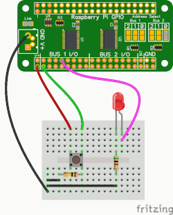
Next, connect the LED and resistor in series between Bus 1 – Pin 8 of the IO Zero 32 and the ground pin, as shown in the picture. Connect your push button between Bus 1 – Pin 1 and the ground pin. Connect a 10K resistor between Bus 1 – Pin 1 and the V+ pin.
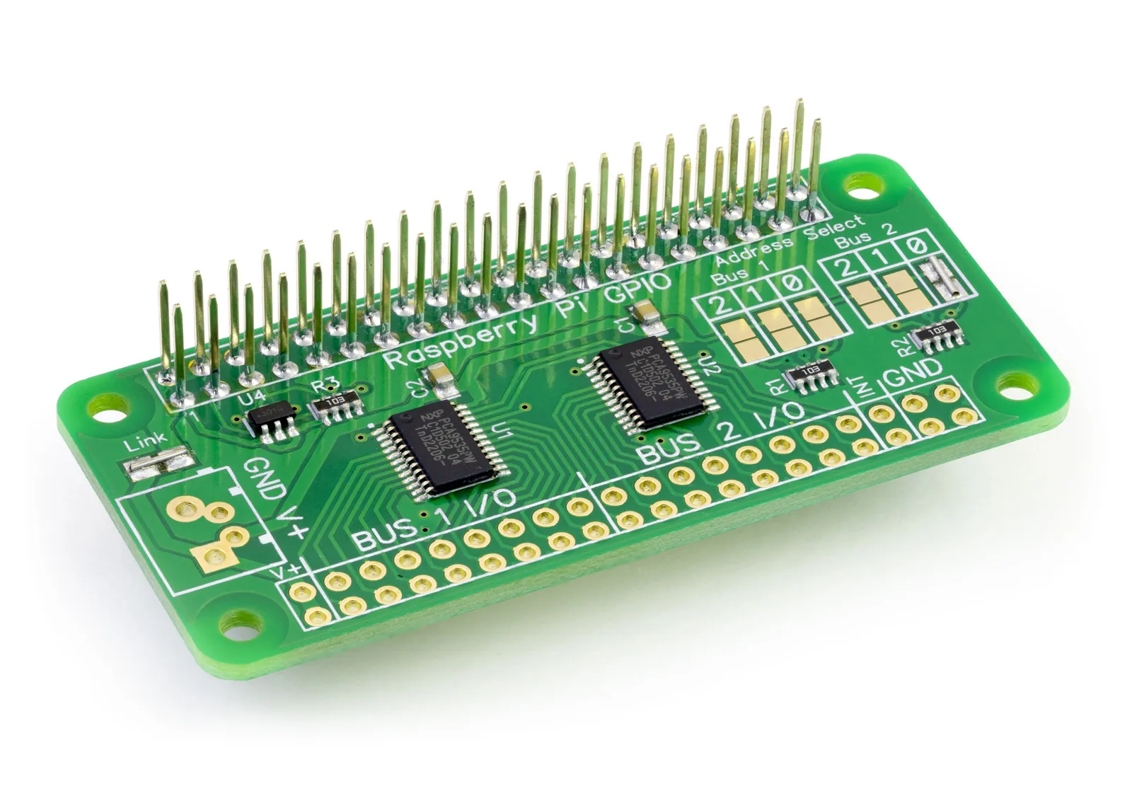
The IO Zero 32 contains two PCA9535 I/O controller chips from NXP. The PCA9535 is an i2c-based controller having 16 I/O pins, which can be configured individually as inputs or outputs. The two PCA9535 controllers are configured on different I2C addresses so you can control them independently from each other; for more information on setting the I2C addresses, see the IO Zero 32 product page.
The maximum current you can draw from any of the pins on the PCA9535 is 50mA, so by using the 500R resistor in series with the LED, we limit the current to a safe level of 10mA at 5V.
We will start by creating a new Python program file called tutorial2.py for this tutorial. You can use your favourite text editor to write the program. You can find a complete example of tutorial2.py in the ABElectronics_Python_Libraries/IOZero32/ folder.
At the top of your program, you must import the IOZero32 library and time library.
#!/usr/bin/env python
from IOZero32 import IOZero32
import time
The IOZero32 library is used for all communication with your IO Zero 32; it gives you control over almost everything that can be done with the PCA9535 controller.
As we will only use one of the PCA9535 controllers, we will create an instance of the IOZero32 class and call it bus. To use both controller chips, you must create two separate instances of the IOZero32 class with the I2C addresses for each chip.
bus = IOZero32(0x20)
0x20 is the I2C address for the controller chip on bus 1; if you have changed the address selection jumpers on your IO Zero 32, you must change this number to match the new address.
With our new instance of the IOZero32 class, we can access all available methods for controlling the IO Zero 32. Let’s begin by setting pin 1 as an input and pin 8 as an output.
bus.set_pin_direction(1, 1)
bus.set_pin_direction(8, 0)
The set_pin-direction method allows us to individually set the direction of each of the 16 pins on the bus.
set_pin-direction takes two variables; the first is the pin you want to control, pins 1 to 16. The second variable is the command byte for setting the pin direction. Setting a pin to 0 makes it an output while setting it to 1 makes it an input; remember, 0 = out, 1 = in.
Next, we will turn off pin 8 with the write_pin method.
bus.write_pin(8,0)
As with setPinDirection, write_pin takes two variables: the first is the pin to write to, and the second is the value to send to the port. Sending a 0 turns a pin off while sending a 1 turns the pin on.
The IO Zero 32 is now set up for turning our LED on and off; we need to set up the button.
We will connect the button between the input on pin 1 and 5V on the V+ pin. When the button is pressed, the input will rise to 5V. We will also need a 100K pull-down resistor connected between the input pin and ground.
The inputs on the IO Zero 32 contain a tiny amount of capacitance. When you release the button, even though the 5V is no longer connected, a small charge will remain on the pin, enough for the IO Zero 32 to get confused and not know if it should read the pin as on or off. A pull-down resistor removes the remaining charge by allowing it to flow to ground.
Now, we have an LED output and a button for input; we can add a while loop where the button-checking code will sit.
while True:
We need to check with an IF statement to see if the button is pressed; this can be done with the read_pin method.
if bus.read_pin(1) == 1:
read_pin takes one variable, the number of the pin to read. It returns a 1 or 0, showing the current state of the pin.
If the button is pressed, we want to show it somehow, so let’s print a message to the screen and light the LED for 2 seconds.
    print("button pressed") # print a message to the screen
    bus.write_pin(8, 1)
    time.sleep(2)
If you run the program now, you will see the LED lights when you press the button, but it will stay on after the button is released and not go out even after the program has ended. We need to add an ELSE statement to the end of the IF statement so it turns the LED off after 2 seconds if the button is no longer pressed.
  else:
     bus.write_pin(8, 0)
This is all the code we need to make the program work; it should now look like this.
from IOZero32 import IOZero32
import time

bus = IOZero32(0x20)
bus.set_pin_direction(1, 1) # set pin 1 as an input
bus.set_pin_direction(8, 0) # set pin 8 as an output
bus.write_pin(8, 0) # turn off pin 8

while True:
  if bus.read_pin(1) == 1: # check to see if the button is pressed
    print("button pressed") # print a message to the screen
    bus.write_pin(8, 1) # turn on the led on pin 8
    time.sleep(2) # wait 2 seconds
  else:
    bus.write_pin(8, 0) # turn off the led on pin 8
Save your program and run it in a command terminal using
python3 tutorial2.py
If everything goes as planned, your LED should turn on for 2 seconds every time you press the button.
(images created with Fritzing)

