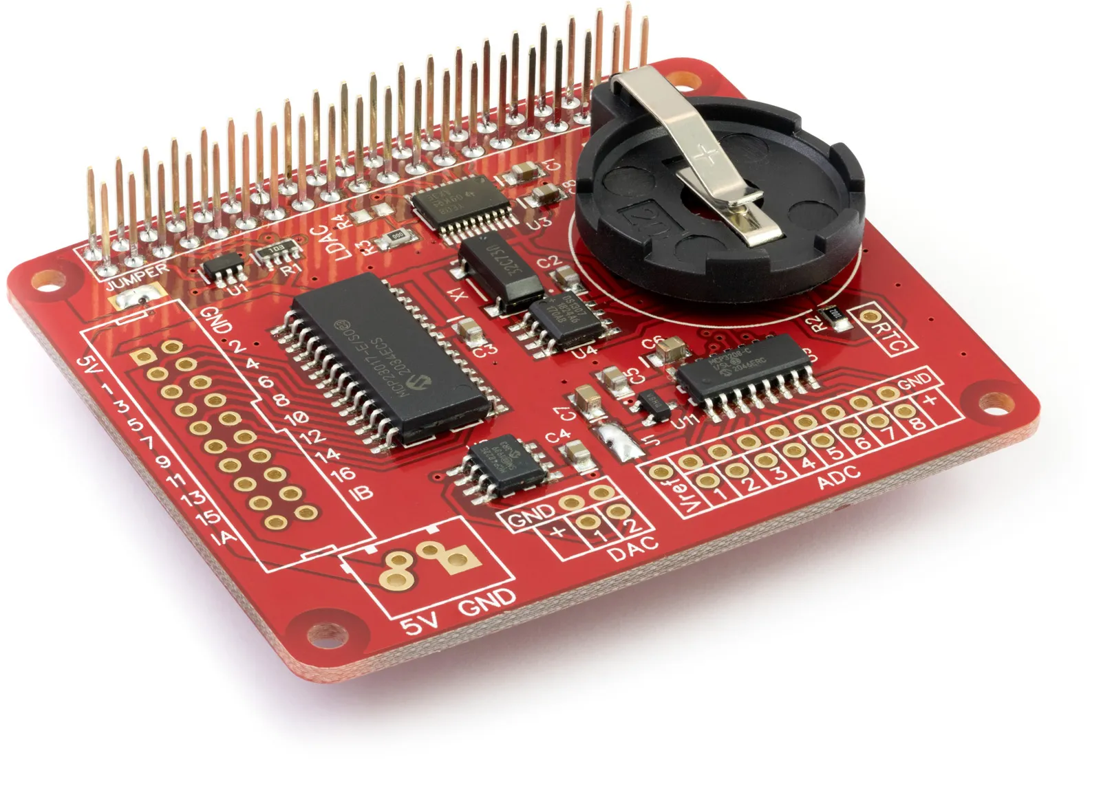
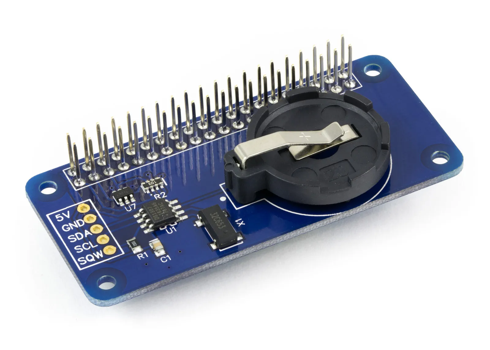
We have been made aware of an issue with the latest Linux kernel used with Raspberry Pi operation systems and the PCF8563 Real-Time Clock IC from NXP, which we use on the Alarm Pi.
The latest kernel version appears to have broken the support for this chip, so it isn’t recognised when using the Linux hwclock to get and set the time and date.
We have withdrawn the sale of this item until the Linux kernel supports the PCF8563 chip again. The board can still be accessed using our demo python scripts, available to download at AlarmPi GitHub Repository.
The RTC Alarm Pi is a real-time clock development board for the Raspberry Pi and is based around the PCF8563 Real-Time Clock IC from NXP. The PCF8563 is controlled via the I2C port on the Raspberry Pi and includes an interrupt-based alarm output, which can be set to pull high at a specified date and time.
Backup power for The RTC Alarm Pi is provided via a 1-farad super-capacitor in place of the lithium coin cell found on most other Real-Time Clock boards. This has the advantage of recharging when the Raspberry Pi is switched on and will not need to be replaced at regular intervals, reducing cost and waste. For greater accuracy, a trimming capacitor is used on the RTC Alarm Pi to fine-tune the 32.768 kHz quartz crystal frequency.
The RTC Alarm Pi is pin-compatible with the Raspberry Pi model B+.
A Microchip PIC12LF1822 microcontroller is included on the RTC Alarm Pi connected to the PCF8563 interrupt pin. When the interrupt is pulled high, the microcontroller sets the High Alarm pin high and the Low Alarm pin low for 500 milliseconds.
Connecting the Low Alarm pin to the reset pin on the Raspberry Pi allows you to put it into a low-power sleep mode and then reset it at a set date and time, waking the Raspberry Pi up. An ICSP (in-circuit serial programming) port is included on the top of the RTC Alarm Pi, allowing you to reprogram the PIC microcontroller for your needs. A wiring diagram for the PIC Micro-controller ICSP port can be found on page 2 of the data sheet.
A 3.3V input port lets you power the real-time clock and microcontroller while the Raspberry Pi is switched off.
The RTC Alarm Pi has direct outputs for the PCF8563 interrupt pin and the Clock output. This can be configured to supply a pulsed output at these frequencies: 32.768 kHz, 1.024 kHz, 32 Hz, and 1 Hz.
Datasheets
Schematic
How to set and read the time
The RTC Alarm Pi requires a Linux kernel with i2c drivers, such as the Occidentalis system image from Adafruit, which has i2c enabled.
To access the RTC Alarm Pi from your Raspberry Pi:
Boot the Pi from that image and execute these commands as root / su user:
First, you need to register the PCF8563 RTC chip with the I2C address of 0x51:
modprobe i2c-dev
modprobe rtc-pcf8563
For Revision One boards use:
echo pcf8563 0x51 > /sys/class/i2c-adapter/i2c-0/new_device
For Revision Two boards use:
echo pcf8563 0x51 > /sys/class/i2c-adapter/i2c-1/new_device
To set the RTC Pi clock with the current system time:
hwclock --systohc
View the current date and time stored in the RTC Pi:
hwclock -r
Set the Linux system time to the value in the RTC Pi:
hwclock –s
To set the RTC Pi with a custom time:
hwclock --set --date="2012-12-25 06:00:12" --utc
Note: documents in Portable Document Format (PDF) require Adobe Acrobat Reader 5.0 or higher to view, download Adobe Acrobat Reader or other PDF reading software for your computer or mobile device.


