The AB Electronics UK Knowledge Base provides support solutions, tutorials and troubleshooting guides.

An analogue-to-digital converter (ADC) is a device that takes real-world signals such as temperature, light, or sound, measured as continuous voltages and converts them into digital values that a computer or microcontroller can understand. This allows a Raspberry Pi or similar device to read data from sensors and use it in programmes. For example, if you’re building a weather station, the ADC allows the Raspberry Pi to read the voltage from a temperature sensor and turn it into a usable number to display or log.
At AB Electronics UK, we sell a range of analogue-to-digital (ADC) development boards for the Raspberry Pi. All of our ADC boards can also be used on other platforms such as the Orange Pi, Asus Tinker Board and Arduino.
This guide will help you choose the best ADC board for your application.
When selecting an ADC, you need to consider the characteristics of the ADC for your needs.
Input voltage range
ADCs typically come in two varieties, single-ended and differential. The difference between single-ended and differential ADCs lies in how they measure voltage:
Single-ended ADC
A single-ended ADC measures the voltage of an input signal relative to ground. This is the most common type and is simpler to use. For example, if a sensor outputs 2.5V and ground is 0V, the ADC reads 2.5V.
The advantage of a single-ended ADC is that it requires fewer wires and is easier to use. The downside is that it is more sensitive to electrical noise and interference.
Differential ADC
A differential ADC measures the voltage difference between two input signals, without using ground as a reference. If one input is 3V and the other is 1V, the ADC reads the difference as 2V.
Differential ADCs are more accurate in noisy environments and better at rejecting interference, but they are slightly more complex to connect and understand.
Bit Mode
The bit mode or resolution of an ADC refers to how precisely it can measure an input voltage. It’s expressed in bits, such as 10-bit, 12-bit, or 17-bit. The higher the number of bits, the more finely the input voltage range can be divided, and the more accurate or sensitive the readings will be.
An ADC converts a continuous voltage into a digital number made up of bits. The number of possible values it can produce is 2n, where n is the number of bits.
- A 10-bit ADC can represent 2¹° = 1024 different values.
- A 12-bit ADC gives 4096 steps.
- A 17-bit ADC gives 131,072 steps.
If your ADC has a voltage range of 0 to 5V and it’s 10-bit, each step represents about 4.88 millivolts (5V ÷ 1024). A 17-bit ADC, on the other hand, could detect changes as small as about 38 microvolts (5V ÷ 131,072).
In simple terms, a higher bit resolution can measure smaller changes in voltage. This means greater sensitivity and more precise measurements from your sensors.
When accuracy matters, like in scientific instruments or precision temperature monitoring, a higher-bit ADC is preferred.
Sample Rate
The sample rate of an ADC (analogue-to-digital converter) refers to how often it measures the input signal. It is usually expressed in samples per second (SPS) or hertz (Hz).
Why it matters:
Imagine you’re recording a sine wave. A higher sample rate means the ADC takes more snapshots of the changing wave per second, resulting in a more accurate digital representation. The same principle applies to any changing signal, like temperature, light, or motion.
For example:
- An ADC with a sample rate of 1000 SPS takes 1000 measurements every second.
- One with 10 SPS samples 10 times per second, which is slower but may use less power and have a higher resolution, making it better for things that change slowly, like room temperature.
In short, the sample rate controls how quickly an ADC can respond to changes in a signal. The right rate depends on what you’re measuring and how fast it changes.
The ADC-DAC Pi Zero and Expander Pi can sample at a rate of several thousand times per second. In contrast, the ADC Pi & ADC Differential Pi can sample between 3.5 and 120 samples per second on each input channel, but at a higher resolution and better accuracy than the faster boards.
Number of channels
The number of channels on an ADC plays an important role in how it can be used in your project.
The number of channels refers to how many separate analogue inputs the ADC can measure. Each channel can be connected to a different sensor or voltage signal.
- A single-channel ADC can only read one signal at a time.
- A multi-channel ADC (e.g., 2, 4 or 8 channels) can measure several signals, one after the other (multiplexed).
If you want to read data from multiple sensors, like temperature, light, and moisture, you’ll need more channels, or you’ll have to use multiple ADCs.
Interface
ADC chips on the Raspberry Pi will connect to either the I2C or SPI bus interfaces.
I2C is slow, but you can connect many more devices to the I2C host machine. Each device is given an I2C address, which can be used in software to select the device.
SPI is fast, but you are limited by the number of devices the SPI bus can accept. On the Raspberry Pi, you can typically connect two devices to the SPI bus.
Choosing the right combination of channel count and interface type depends on how many signals you need to measure and how quickly you need the data.
Choosing an ADC
How many inputs do you need to measure?
Up to two inputs:
The ADC-DAC Pi Zero is a 2-channel 12-bit high-speed analogue-to-digital converter, which measures voltages between 0 and 3.3 Volts.
More than two inputs:
Do you need to read single-ended inputs?
The ADC Pi is an 8-channel, 17-bit analogue-to-digital converter that measures 0 and 5 Volts using its onboard voltage divider. The ADC Pi can be stacked to give you up to 32 analogue inputs. Higher voltages can be measured by adding a resistor in series with the input. See our ADC Input Resistor Calculator to find the correct resistor value.
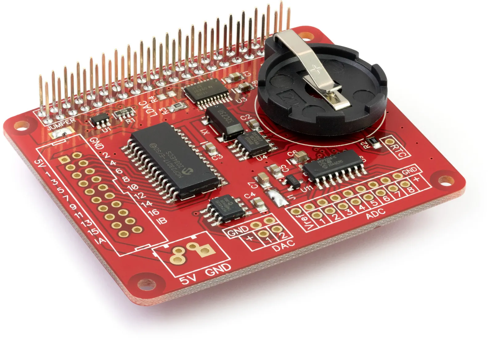
The Expander Pi is an 8-channel, 12-bit analogue-to-digital converter that measures 0 and 4.096 Volts.
Do you need to be able to read differential voltage inputs?
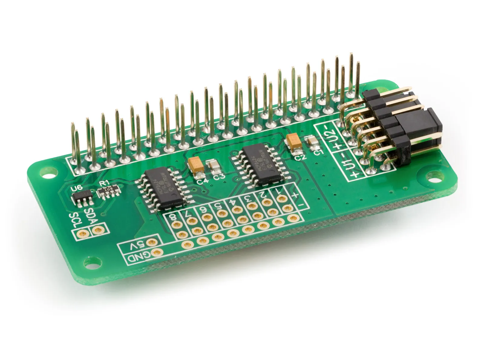
ADC Differential Pi is an 8-channel 18-bit analogue-to-digital converter which allows you to measure an input range of -2.048 volts to + 2.048 volts on each channel. The voltage range can be increased using a voltage divider or an operational amplifier (OP-AMP).
Also useful for your Raspberry Pi project
Temperature & Sensing
1 Wire Pi Plus
Connect dozens of 1-Wire sensors - temperature, iButtons, EEPROMs - via a single GPIO pin. Stacks directly on the 40-pin header.
Analogue I/O
ADC Pi
Read up to 8 analogue inputs - perfect for pairing with your temperature sensors or other analogue-output devices.
All-in-one
Expander Pi
Combines ADC, DAC, 32 GPIO ports and a real-time clock on one board. The most versatile board for complex Raspberry Pi projects.
Related Articles
Order these Boards
ADC Differential Pi
8 Channel 18-bit Differential Analogue to Digital converter development board for the Raspberry Pi
£16.99 ex VAT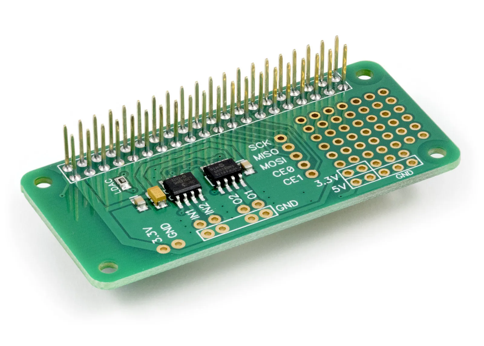
ADC-DAC Pi Zero
2 Channel ADC and 2 Channel DAC development board for the Raspberry Pi
£12.49 ex VAT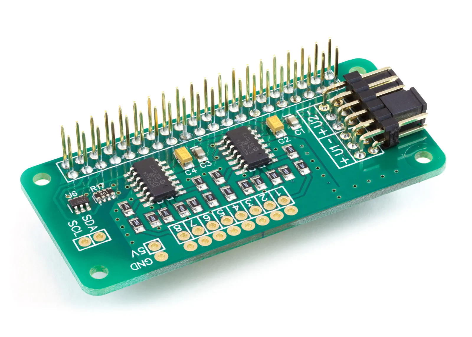
ADC Pi
8 Channel 17-bit Single-Ended Analogue to Digital Converter for the Raspberry Pi and Single-Board Computers
£17.99 ex VAT