The AB Electronics UK Knowledge Base provides support solutions, tutorials and troubleshooting guides.

YOU WILL NEED THIS BOARD
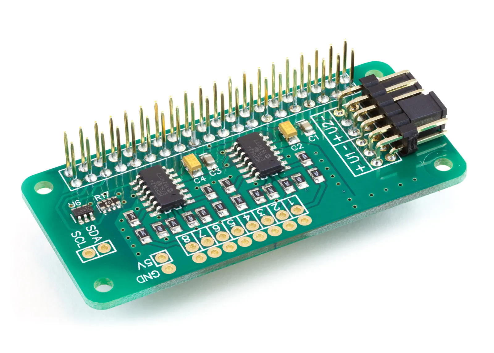
ADC Pi
8 Channel 17-bit Single-Ended Analogue to Digital Converter for the Raspberry Pi and Single-Board Computers
£16.19 ex VAT
In this tutorial, we will use the ADC Pi to build a data logger. It reads the voltage on all eight analogue inputs once a second and appends each set of readings, with a timestamp, to a CSV file you can open in any spreadsheet. You will need your Raspberry Pi and an ADC Pi. Whatever you want to measure connects to the eight input channels on the ADC Pi screw terminals, between an input and the adjacent ground.
We will use the AB Electronics Python library to talk to the ADC Pi. To download the library, visit our Python Library and Demos knowledge base article.
You must enable I2C on your Raspberry Pi; see our tutorial on I2C: I2C Part 2 - Enabling I2C on the Raspberry Pi.
The AB Electronics Python library uses another library called python3-smbus; you can install it using apt-get with the following commands.
    sudo apt-get update
    sudo apt-get install python3-smbus
With the libraries installed and the Raspberry Pi configured to use I2C, we can begin building our data logger.
Stage 1 – Connecting the ADC Pi
If you haven't done so, install your ADC Pi onto the Raspberry Pi by connecting it to the GPIO header. Make sure your Raspberry Pi is turned off when you do this to minimise the risk of damaging the Raspberry Pi or the ADC Pi.
The ADC Pi contains two MCP3424 analogue-to-digital converter chips from Microchip. Each chip provides four single-ended input channels, giving eight channels in total. The two chips are set to different I2C addresses, 0x68 and 0x69 by default, so the library can talk to each one independently. Channels 1 to 4 are on the chip at address 0x68, and channels 5 to 8 are on the chip at address 0x69. If you have changed the address selection jumpers on your ADC Pi, you must use the new addresses in your program.
Each input is measured against the ground pin next to it and can read from 0V up to 5V. If you need to measure a higher voltage, you can scale it down with a voltage divider first; our ADC Pi Input Voltage Calculator will work out the resistor values for you.

Stage 2 – Choosing the bit mode and sample rate
Before we write any code, we need to decide which bit mode to run the ADC Pi in, and this is the part of the project that catches people out, so it is worth understanding.
The MCP3424 can convert at four resolutions, and the resolution you choose sets how long each conversion takes. The higher the resolution, the longer the chip needs to produce a reading.
| Library bit setting | Conversion rate | Time per conversion |
|---|---|---|
| 12 | 240 samples/sec | ~4 ms |
| 14 | 60 samples/sec | ~17 ms |
| 16 | 15 samples/sec | ~67 ms |
| 18 | 3.75 samples/sec | ~267 ms |
Our logger reads the eight channels one after another, so each logging cycle is roughly the cost of eight conversions back to back. That is where the bit mode matters.
In 18-bit mode the chip manages only 3.75 samples a second, so a single conversion takes about 267 ms. Eight of them take a little over two seconds, which is already longer than the one-second interval we are aiming for. You simply cannot read all eight channels inside a second at 18-bit.
In 16-bit mode the chip runs at 15 samples a second, so each conversion takes about 67 ms. Eight conversions take around half a second, leaving comfortable headroom inside the one-second interval. This is why the logger uses 16-bit mode.
There is one detail specific to the ADC Pi worth noting. Because the ADC Pi uses the MCP3424 in a single-ended input arrangement, each mode gives one bit less resolution than the chip's differential figure. So the 16-bit setting you pass to the library samples at 15-bit resolution on the ADC Pi. Fifteen bits gives 32,768 steps across the input range, or a resolution of about 0.15 mV, which is more than enough for most logging work. You can see the full breakdown for every mode in our ADC Bit Modes and Resolution article.
In short: 16-bit mode is the fastest setting that still lets us capture all eight channels every second, and on the ADC Pi it gives us 15-bit resolution to work with.
Stage 3 – Writing the data logger
We will create a new Python program file called adc_datalogger.py for this tutorial. You can use your favourite text editor to write the program. You can also find a ready-made version called demo_logvoltage.py in the ABElectronics_Python_Libraries/ADCPi/demos/ folder.
At the top of your program, you will need to import three libraries.
#!/usr/bin/env python
import time
import datetime
from ADCPi import ADCPi
The ADCPi library is used for all communication with the ADC Pi. The time library gives us the sleep and timing functions we will use to pace the logger, and the datetime library lets us stamp each reading with the current date and time.
Next, we create an instance of the ADCPi class and call it adc.
adc = ADCPi(0x68, 0x69, 16)
The ADCPi class takes three values. The first two are the I2C addresses of the two MCP3424 chips, 0x68 and 0x69, the same addresses we covered in Stage 1. The third value is the bit mode, and as we worked out in Stage 2, we use 16 so that all eight channels can be read inside one second.
Now we will set up the timing for the logger.
interval = 1.0  # sample interval in seconds
next_run = time.monotonic()  # time of the next sample
interval is how often we want a reading, in seconds. next_run holds the time the next reading is due. We use time.monotonic() for this rather than the wall clock; it returns a steadily increasing count that is not affected by changes to the system time, which makes it a reliable basis for timing.
Let us print a message so we know the logger has started, then begin the main loop.
print("Logging...")

while True:
    next_run += interval
At the top of each pass we add one interval to next_run, so it always holds the time the current reading is due. Advancing the target by a fixed amount each pass, rather than measuring from the end of the previous sleep, stops the logger from drifting even though each set of readings takes a fraction of a second to complete.
Next, we open the log file.
file = open('adc_log.csv', 'a') # open the log file for appending
Opening the file with 'a' adds to the end of the file rather than overwriting it, so each new row is written below the last. Opening and closing the file inside the loop means every reading is committed to disk as it is taken; if the Raspberry Pi loses power, you lose only the row in progress, not the whole log.
Now we write the timestamp.
    timestamp = datetime.datetime.now().strftime("%Y-%m-%d %H:%M:%S.%f")[:-3]
    file.write(timestamp + ",")  # write the current time to the log file
strftime formats the date and time as text. The format string gives the date and time down to microseconds, and the [:-3] trims the last three digits so the time is recorded to the millisecond. We add a comma after it so the timestamp sits in its own column.
With the time recorded, we read each of the eight channels and write the voltages to the file.
    file.write("%02f," % adc.read_voltage(1))
    file.write("%02f," % adc.read_voltage(2))
    file.write("%02f," % adc.read_voltage(3))
    file.write("%02f," % adc.read_voltage(4))
    file.write("%02f," % adc.read_voltage(5))
    file.write("%02f," % adc.read_voltage(6))
    file.write("%02f," % adc.read_voltage(7))
    file.write("%02f\n" % adc.read_voltage(8))
read_voltage takes one value, the channel number from 1 to 8, and returns the voltage on that input as a floating-point number, already scaled to allow for the input arrangement on the ADC Pi. Each voltage is written as a decimal number followed by a comma so the file stays comma-separated. The eighth and final value ends with \n instead of a comma, which moves the file on to a new line ready for the next reading.
We then close the file.
file.close()
Finally, we wait until the next reading is due.
    sleep_time = next_run - time.monotonic()
    if sleep_time > 0:
        time.sleep(sleep_time)
We work out how much of the second is left by subtracting the current time from next_run, then sleep for that long. If the readings happened to take longer than the interval, sleep_time will be zero or negative, so we skip the sleep and carry straight on to the next pass rather than falling further behind.
This is all the code we need to make the logger work; it should now look like this.
#!/usr/bin/env python
import time
import datetime
from ADCPi import ADCPi

adc = ADCPi(0x68, 0x69, 16)  # I2C addresses 0x68 and 0x69, 16-bit mode

interval = 1.0  # sample interval in seconds
next_run = time.monotonic()  # time of the next sample

print("Logging...")

while True:
    next_run += interval

    file = open('adc_log.csv', 'a')  # open the log file for appending

    timestamp = datetime.datetime.now().strftime("%Y-%m-%d %H:%M:%S.%f")[:-3]
    file.write(timestamp + ",")  # write the current time to the log file

    # read each of the 8 channels and write the voltage to the log file
    file.write("%02f," % adc.read_voltage(1))
    file.write("%02f," % adc.read_voltage(2))
    file.write("%02f," % adc.read_voltage(3))
    file.write("%02f," % adc.read_voltage(4))
    file.write("%02f," % adc.read_voltage(5))
    file.write("%02f," % adc.read_voltage(6))
    file.write("%02f," % adc.read_voltage(7))
    file.write("%02f\n" % adc.read_voltage(8))

    file.close()

    # wait until it is time for the next sample
    sleep_time = next_run - time.monotonic()
    if sleep_time > 0:
        time.sleep(sleep_time)
Save your program and run it in a command terminal using
python3 adc_datalogger.py
If everything goes as planned, the program will print Logging... and then write one line a second to a file called adc_log.csv in the same folder. Each line holds the timestamp followed by the eight channel voltages. Leave it running for as long as you want to record, then stop it by pressing Ctrl+C.
You can open adc_log.csv in LibreOffice Calc, Microsoft Excel, or any other spreadsheet. The first column is the timestamp and the next eight columns are the voltages from channels 1 to 8, ready to chart or analyse.
To run the logger unattended, you can start it from a systemd service or a cron @reboot job so logging begins automatically when the Raspberry Pi boots.
You can view and download the demo script and Python library from our Python Libraries GitHub Repository.
Also useful for your Raspberry Pi project
Temperature & Sensing
1 Wire Pi Plus
Connect dozens of 1-Wire sensors - temperature, iButtons, EEPROMs - via a single GPIO pin. Stacks directly on the 40-pin header.
Analogue I/O
ADC Pi
Read up to 8 analogue inputs - perfect for pairing with your temperature sensors or other analogue-output devices.
All-in-one
Expander Pi
Combines ADC, DAC, 32 GPIO ports and a real-time clock on one board. The most versatile board for complex Raspberry Pi projects.
Chapters
Related Articles
- Getting Started with the ADC Pi
- ADC Pi - Plotting Voltages in a GUI
- ADC Pi Data Logger
- ADC Pi FAQ
- ADC Pi with ACS712
- ADC Pi with Capacitive Soil Sensor
- ADC Pi with HIH-4000
- ADC Pi with Raspberry Pi Pico
- ADC Pi with TMP36
- ADC Sample Rate Comparison
- Using 4-20mA sensors with the ADC Pi
- Using the ADC Pi with Arduino
- Using the ADC Pi with Home Assistant on the Raspberry Pi
Order these Boards
ADC Pi
8 Channel 17-bit Single-Ended Analogue to Digital Converter for the Raspberry Pi and Single-Board Computers
£16.19 ex VAT