The AB Electronics UK Knowledge Base provides support solutions, tutorials and troubleshooting guides.

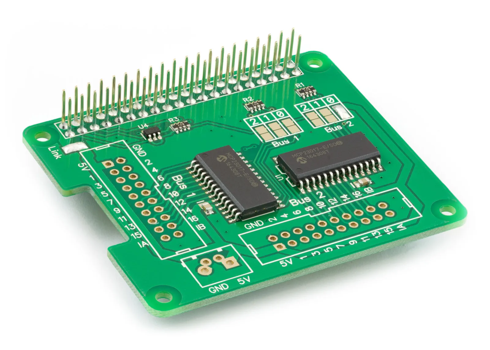
YOU WILL NEED THIS BOARD
In 2017 we released the design files for a relay board to work with our IO Pi Plus interface board. We made the design and Gerber files public, so anyone can make their own or modify the design to fit their needs. We are releasing the design files for an opto-isolated input board to accompany the relay board.
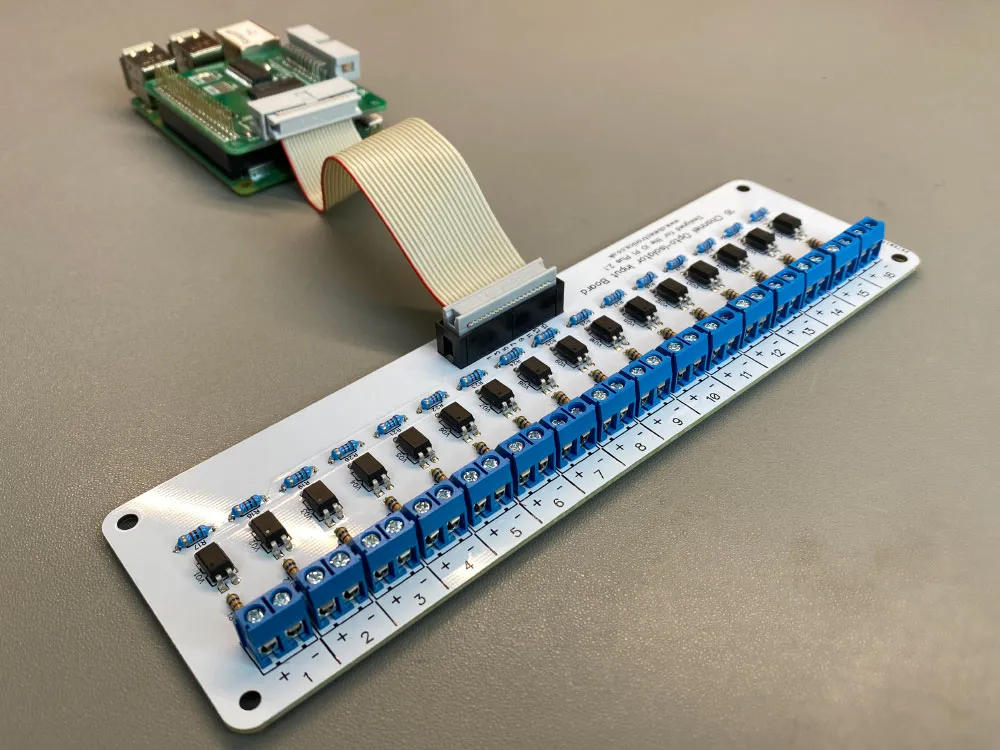
The 16-channel opto-isolated input board can be used with the IO Pi Plus version 2.1 or later and the IO Pi Zero. The board is designed to work with the FOD817C300 optoisolator from Fairchild Semiconductor, but it should work with any 4-pin transistor optoisolator that uses the same pin configuration.
To build the relay board, you will need the following parts:
- VO1 to VO16: 16 x FOD817C300 optoisolator
- R1 to R16: 0.25W Resistor (see below for calculating values)
- R17 to R32: 1K 0.25W Resistor
- 1 x 20 pin IDC PCB connector (2.54mm pitch)
- 16 x 2 pin 5.08mm screw terminals or another compatible connector. (5.00mm will also work)
IDC Connector
The 20-pin IDC connector uses the same pin configuration as the IO Pi Plus 2.1, so you can connect the two using two 20-pin IDC connectors and a ribbon cable. The input numbers match the pin numbering on the IO Pi Plus bus making it easy to read the inputs using our IO Pi software libraries.
Input Resistors
The input resistors R1 to R16 must be specified for the input voltage. The emitter for the FOD817C300 opto-isolator requires a maximum current of 20mA at 1.2V. Our LED resistor calculator can be used to find the required resistance. For example, a 560R resistor will give a usable input voltage range of 3V to 12V.
PCB Files
The PCB dimensions are 60mm x 200mm. Gerber files are included in the GitHub repository and use a file name format compatible with several PCB manufacturers, including JLC PCB and Elecrow. The “Gerber Files.zip” file contains a zip of the Gerber files that can be uploaded directly to the PCB manufacturer of your choice. The schematic and PCB files are included in Diptrace format; you can download a free version from Diptrace.
The design and Gerber files for the input board are available to download from our GitHub repository.
Note: The input board can be used with older versions of the IO Pi Plus and IO Pi Zero, as well as the original IO Pi, but you will need only to connect the 16 input pins on the IDC connector. The ground pin must be connected separately to the GND pin on the IO Pi board, as earlier models did not include the ground on the IDC header. The input numbers will also not match the inputs on the IO Pi.
Also useful for your Raspberry Pi project
Temperature & Sensing
1 Wire Pi Plus
Connect dozens of 1-Wire sensors - temperature, iButtons, EEPROMs - via a single GPIO pin. Stacks directly on the 40-pin header.
Analogue I/O
ADC Pi
Read up to 8 analogue inputs - perfect for pairing with your temperature sensors or other analogue-output devices.
All-in-one
Expander Pi
Combines ADC, DAC, 32 GPIO ports and a real-time clock on one board. The most versatile board for complex Raspberry Pi projects.
Related Articles
- IO Pi Plus FAQ
- IO Pi Plus Tutorial 1 - The Blinking LED
- IO Pi Plus Tutorial 2 - Push the Button
- IO Pi Plus Tutorial 3 - Introducing Interrupts
- IO Pi Plus Tutorial 4 - More Interrupts
- IO Pi Plus Tutorial - MQTT Reading the Ports
- IO Pi Plus with Raspberry Pi Pico
- IO Pi Plus Tutorial - MQTT Control
- Driving Relays or Higher Loads with the IO Pi Plus
- Relay Board for the IO Pi Plus 2.1
- 16 Channel Opto-Isolated Input Board