The AB Electronics UK Knowledge Base provides support solutions, tutorials and troubleshooting guides.

YOU WILL NEED THIS BOARD
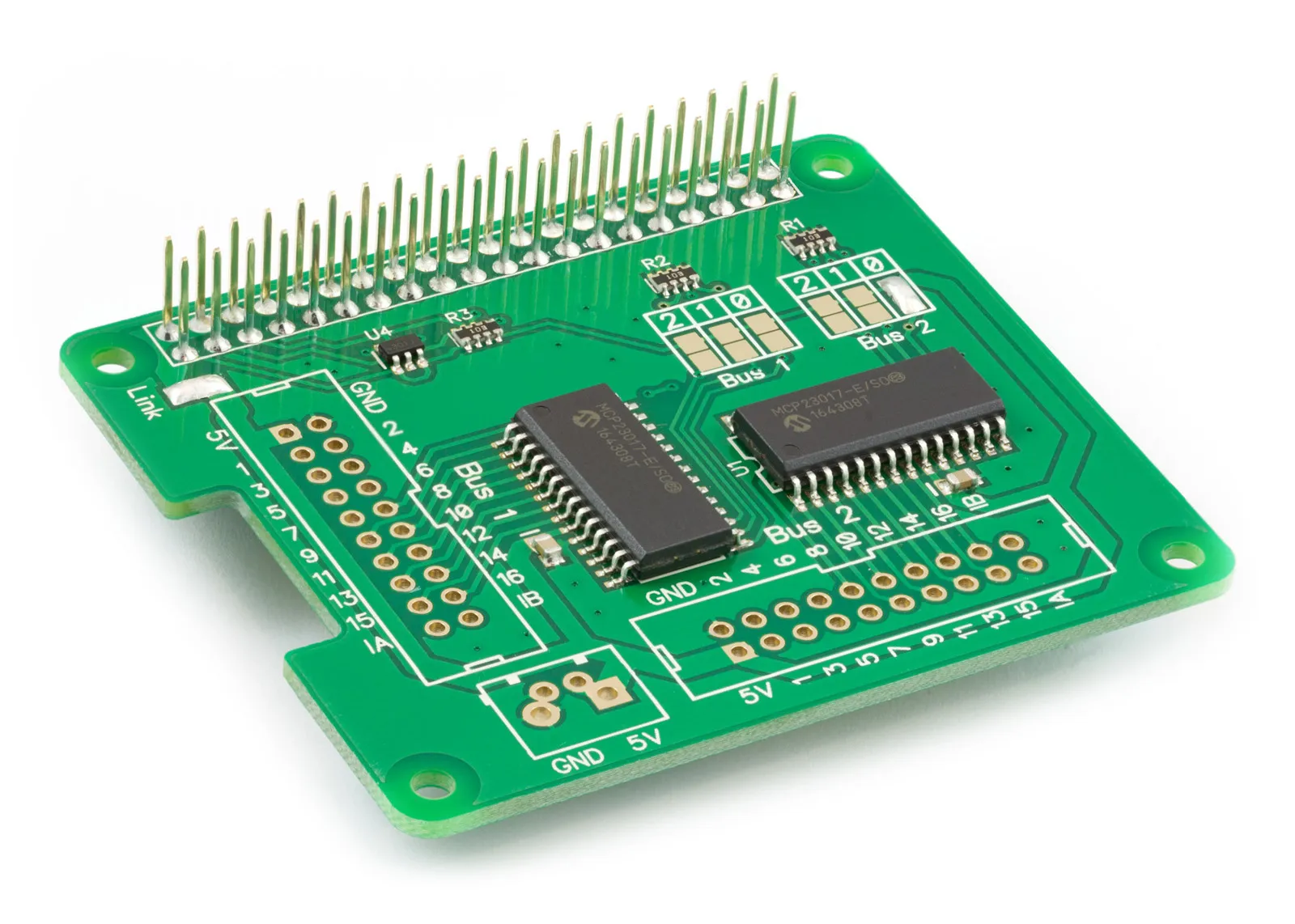
This tutorial will setup the IO Pi Plus to use with Home Assistant Operation System on your Raspberry Pi.
This custom component is designed to run the IO Pi Plus Raspberry Pi development board from AB Electronics UK with Home Assistant Operating System. Up to four IO Pi Plus boards can be used together on a Raspberry Pi adding add up to 128 input and output channels to Home Assistant to act as either switches or input sensors. This makes the IO Pi Plus ideal for large-scale GPIO projects.
The IO Pi Plus uses the Microchip MCP23017 GPIO expanders and this library is based on the Home Assistant MCP23017 integration modified to use our own IOPi Python library from abelectronics.co.uk/kb/article/23/python-library-and-demos
Note: Microchip recommends that pin 8 (GPA7) and pin 16 (GPB7) are used as outputs only. This change was made for revision D MCP23017 chips manufactured after June 2020. See the MCP23017 datasheet for more information.
This component will enable the following platforms.
- binary_sensor: Show pin status True or False.
- switch: Switch pin status True or False.
I2C Support Required
First you will need to enable I2C support in the Home Assistant Operating System, we have a tutorial to enable I2C.
Installation and Configuration
To be able to install the custom components for the IO Pi you need to be able to edit files in your configuration directory / folder.
We recommend using either the Samba add on or Studio Code Server which allows you to use Visual Code within Home Assistant.
Download the custom component from GitHub and extract to a directory on your computer.
- Using your tool of choice, open the directory (folder) for your HA configuration (where you find configuration.yaml).
- If you do not have a custom_components directory (folder) there, you need to create it.
- In the custom_components directory (folder) create a new folder called abelectronicsiopi.
- Copy all the files from the custom_components/abelectronicsiopi/ directory (folder) to the new abelectronicsiopi directory (folder).
- Restart Home Assistant
Using your HA configuration directory (folder) as a starting point you should now also have this:
custom_components/abelectronicsiopi/__init__.py
custom_components/abelectronicsiopi/binary_sensor.py
custom_components/abelectronicsiopi/IOPI.py
custom_components/abelectronicsiopi/manifest.json
custom_components/abelectronicsiopi/switch.py
Example configuration.yaml
binary_sensor:
  - platform: abelectronicsiopi
    i2c_address: 0x20
    scan_interval: 1
    invert_logic: false
    pull_mode: true
    pins:
      1: Pin 1 Sensor
      2: Pin 2 Sensor
      3: Pin 3 Sensor

switch:
  - platform: abelectronicsiopi
    i2c_address: 0x21
    invert_logic: false
    pins:
      1: Pin 1 Switch
      2: Pin 2 Switch
      3: Pin 3 Switch
Usage
Binary Sensor Configuration Variables
The binary_sensor component uses the following variables to configure the sensor
| Key | Type | Required | Description |
|---|---|---|---|
i2c_address |
Hex |
True |
This contains the I2C address of the MCP23017 device. The default I2C addresses on the IO Pi Plus are 0x20 and 0x21. |
scan_interval |
Integer |
True |
This contains the scan interval in seconds between reading the device or pins in seconds. |
invert_logic |
Boolean |
False |
This boolean value (true / false) allows you to invert the polarity of the selected pin. |
pull_mode |
Boolean |
False |
This boolean value (true / false) enables or disables the internal 100K pull-up resistors for an individual pin. |
pins |
Array |
True |
This contains an array of the pins of the MCP23017 device numbered 1 to 16 with the pin number followed by the custom pin name. |
Editing the configuration.yaml file to add the binary sensor
Using the text editor of choice open the configuration.yaml for your HA configuration.
Add a new binary_sensor with the following code:
binary_sensor:
   - platform: abelectronicsiopi
Add the following attributes to setup the component:
i2c_address: 0x20
scan_interval: 1
invert_logic: false
pull_mode: true
Add the pins array for the component:
pins:
  1: Pin 1 Sensor
  2: Pin 2 Sensor
  3: Pin 3 Sensor
  4: Pin 4 Sensor
  5: Pin 5 Sensor
  6: Pin 6 Sensor
  7: Pin 7 Sensor
  8: Pin 8 Sensor
  9: Pin 9 Sensor
  10: Pin 10 Sensor
  11: Pin 11 Sensor
  12: Pin 12 Sensor
  13: Pin 13 Sensor
  14: Pin 14 Sensor
  15: Pin 15 Sensor
  16: Pin 16 Sensor
The completed YMAL code should look like this:
binary_sensor:
  - platform: abelectronicsiopi
    i2c_address: 0x20
    scan_interval: 1
    invert_logic: false
    pull_mode: true
    pins:
      1: Pin 1 Sensor
      2: Pin 2 Sensor
      3: Pin 3 Sensor
      4: Pin 4 Sensor
      5: Pin 5 Sensor
      6: Pin 6 Sensor
      7: Pin 7 Sensor
      8: Pin 8 Sensor
      9: Pin 9 Sensor
      10: Pin 10 Sensor
      11: Pin 11 Sensor
      12: Pin 12 Sensor
      13: Pin 13 Sensor
      14: Pin 14 Sensor
      15: Pin 15 Sensor
      16: Pin 16 Sensor
After a restart you can now add the sensor into the user interface.
Switch Configuration Variables
The switch component uses the following variables to configure the switch
| Key | Type | Required | Description |
|---|---|---|---|
i2c_address |
Hex |
True |
This contains the I2C address of the MCP23017 device. The default I2C addresses on the IO Pi Plus are 0x20 and 0x21. |
invert_logic |
Boolean |
True |
This boolean value (true / false) allows you to invert the polarity of the selected pin. |
pins |
Array |
True |
This contains an array of the pins of the MCP23017 device numbered 1 to 16 with the pin number followed by the custom pin name. |
Editing the configuration.yaml file to add the binary sensor
Using the text editor of choice open the configuration.yaml for your HA configuration.
Add a new switch with the following code:
switch:
   - platform: abelectronicsiopi
Add the following attributes to setup the component:
i2c_address: 0x21
invert_logic: false
Add the pins array for the component:
pins:
  1: Pin 1 Switch
  2: Pin 2 Switch
  3: Pin 3 Switch
  4: Pin 4 Switch
  5: Pin 5 Switch
  6: Pin 6 Switch
  7: Pin 7 Switch
  8: Pin 8 Switch
  9: Pin 9 Switch
  10: Pin 10 Switch
  11: Pin 11 Switch
  12: Pin 12 Switch
  13: Pin 13 Switch
  14: Pin 14 Switch
  15: Pin 15 Switch
  16: Pin 16 Switch
The completed YMAL code should look like this:
switch:
  - platform: abelectronicsiopi
    i2c_address: 0x21
    invert_logic: false
    pins:
      1: Pin 1 Switch
      2: Pin 2 Switch
      3: Pin 3 Switch
      4: Pin 4 Switch
      5: Pin 5 Switch
      6: Pin 6 Switch
      7: Pin 7 Switch
      8: Pin 8 Switch
      9: Pin 9 Switch
      10: Pin 10 Switch
      11: Pin 11 Switch
      12: Pin 12 Switch
      13: Pin 13 Switch
      14: Pin 14 Switch
      15: Pin 15 Switch
      16: Pin 16 Switch
You can now add the sensors into the user interface.
Demo UI Cards
type: entities
entities:
  - entity: binary_sensor.pin_1_sensor
  - entity: binary_sensor.pin_2_sensor
  - entity: binary_sensor.pin_3_sensor
  - entity: binary_sensor.pin_4_sensor
  - entity: binary_sensor.pin_5_sensor
  - entity: binary_sensor.pin_6_sensor
  - entity: binary_sensor.pin_7_sensor
  - entity: binary_sensor.pin_8_sensor
  - entity: binary_sensor.pin_9_sensor
  - entity: binary_sensor.pin_10_sensor
  - entity: binary_sensor.pin_11_sensor
  - entity: binary_sensor.pin_12_sensor
  - entity: binary_sensor.pin_13_sensor
  - entity: binary_sensor.pin_14_sensor
  - entity: binary_sensor.pin_15_sensor
  - entity: binary_sensor.pin_16_sensor
title: IO Pi Inputs

type: entities
entities:
  - entity: switch.pin_1_switch
  - entity: switch.pin_2_switch
  - entity: switch.pin_3_switch
  - entity: switch.pin_4_switch
  - entity: switch.pin_5_switch
  - entity: switch.pin_6_switch
  - entity: switch.pin_7_switch
  - entity: switch.pin_8_switch
  - entity: switch.pin_9_switch
  - entity: switch.pin_10_switch
  - entity: switch.pin_11_switch
  - entity: switch.pin_12_switch
  - entity: switch.pin_13_switch
  - entity: switch.pin_14_switch
  - entity: switch.pin_15_switch
  - entity: switch.pin_16_switch
title: IO Pi Outputs
Also useful for your Raspberry Pi project
Temperature & Sensing
1 Wire Pi Plus
Connect dozens of 1-Wire sensors - temperature, iButtons, EEPROMs - via a single GPIO pin. Stacks directly on the 40-pin header.
Analogue I/O
ADC Pi
Read up to 8 analogue inputs - perfect for pairing with your temperature sensors or other analogue-output devices.
All-in-one
Expander Pi
Combines ADC, DAC, 32 GPIO ports and a real-time clock on one board. The most versatile board for complex Raspberry Pi projects.
Chapters
Related Articles
- Using 1 Wire with Home Assistant and the Raspberry Pi OS
- Using I2C Devices on the Raspberry Pi with Home Assistant
- Using the IO Pi Plus with Home Assistant on the Raspberry Pi
- Using the ADC Pi with Home Assistant on the Raspberry Pi
- Using the ADC Differential Pi with Home Assistant on the Raspberry Pi