The AB Electronics UK Knowledge Base provides support solutions, tutorials and troubleshooting guides.

YOU WILL NEED THIS BOARD
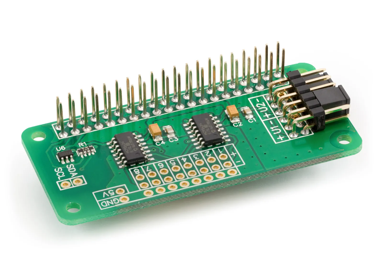
ADC Differential Pi
8 Channel 18-bit Differential Analogue to Digital converter development board for the Raspberry Pi
£16.99 ex VAT
This tutorial will use the ADC Differential Pi or DeltaSigma Pi with an ADXL335 from Analog Devices on a SparkFun Triple Axis Accelerometer Breakout to make a digital accelerometer. You will need your Raspberry Pi, an ADC Differential Pi or DeltaSigma Pi, and a SparkFun Triple Axis Accelerometer Breakout.
We will use the AB Electronics Python library to talk to the ADC Differential Pi. To download the library, visit our Python Library and Demos knowledge base article.
You must enable I2C on your Raspberry Pi; see our other tutorial on i2c: I2C Part 2: Using I2C on the Raspberry Pi.
The AB Electronics Python library uses another library called python3-smbus; you can install it using apt-get with the following commands.
sudo apt-get update
sudo apt-get install python3-smbus
With the libraries installed and the Raspberry Pi configured to use i2c, we can begin building our project.
Parts Used:
ADXL335 SparkFun Triple Axis Accelerometer Breakout (Datasheet)
3 x 18K Resistor
3 x 27K Resistor
Connecting Wire
Connecting the Sensor to the ADC Differential Pi Plus
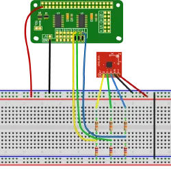 If you haven't done so, install your ADC Differential Pi Plus onto the Raspberry Pi by connecting it to the GPIO header. Make sure your Raspberry Pi is turned off when you do this to minimise the risk of damaging the Raspberry Pi or the ADC Differential Pi Plus.
Connect the VCC pin on the ADXL335 board to 3.3V on the GPIO header.
Connect the GND on the ADXL335 to GND on the GPIO header.
On the ADC Differential Pi, connect the negative inputs on channels 1, 2 and 3 to GND; this sets the ADC chips into the single-ended mode to measure between 0 and 2.048 volts.
Now we need to connect the output from the ADXL335 board to the ADC inputs; as the output from the ADXL335 is up to 3.3 volts, we need to add a voltage divider between the ADXL335 output and the ADC Differential Pi positive inputs on each channel.
Connect the X pin on the ADXL335 to an 18K resistor, connect the other side of the resistor to input 1 on the ADC Differential Pi and connect the 27K resistor between pin 1 on the ADC Differential Pi and GND.
Connect the Y pin on the ADXL335 to an 18K resistor, connect the other side of the resistor to input 2 on the ADC Differential Pi and connect the 27K resistor between pin 2 on the ADC Differential Pi and GND.
Connect the Z pin on the ADXL335 to an 18K resistor, connect the other side of the resistor to input 3 on the ADC Differential Pi and connect the 27K resistor between pin 3 on the ADC Differential Pi and GND.
For this tutorial, we will create a new Python program file called demo-adxl335.py. You can use your favourite text editor to write the program. You can find a complete example of demo-adxl335.py in the ABElectronics_Python_Libraries/ADCDifferentialPi/ folder.
At the top of your program, you must import the ADCDifferentialPi library and time library. We also add variables to hold the values related to the sensor data conversion.
#!/usr/bin/env python
from ADCDifferentialPi import ADCDifferentialPi
import time
import os
The ADCDifferentialPi library is used for all communication with your ADC Differential Pi Plus; it gives you control over almost everything that can be done with the MCP3424 controller.
Next, we need to create an instance of the ADCDifferentialPi class and call it adc.
adc = ADCDifferentialPi(0x68, 0x69, 12)
0x68 and 0x69 are the I2C address for the ADC chips; if you have changed the address selection jumpers on your ADC Differential Pi Plus, you must change these numbers to match the new addresses.
Now we add variables which will be used to hold the sensor readings.
# the conversion factor is the ratio of the voltage divider on the inputs
conversionfactor = 1.666
# setup these static values when the sensor is not moving
xStatic = 0
yStatic = 0
zStatic = 0
xMax = 0
xMin = 0
yMax = 0
yMin = 0
zMax = 0
zMin = 0
We need to initialise the static values with the sensor readings when the sensor board is not moving; this code loops 50 times and averages the sensors readings to get a not moving reading.
# get 50 samples from each ADC channel and use that to get an average value for 0G.
# Keep the accelerometer still while this part of the code is running
for x in range(0, 50):
    xStatic = xStatic + adc.read_voltage(1)
    yStatic = yStatic + adc.read_voltage(2)
    zStatic = zStatic + adc.read_voltage(3)
    xStatic = (xStatic / 50) * conversionfactor
    yStatic = (yStatic / 50) * conversionfactor
    zStatic = (zStatic / 50) * conversionfactor
We will need a loop so that the same commands can run repeatedly. This can be done with a simple while loop.
while True:
As True is always true, the while loop will continue until you exit the program with a Ctrl-C.
We must read from each X, Y and Z output and process the values.
# read from adc channels and print to screen
xVoltage =  (adc.read_voltage(1) * conversionfactor) - xStatic
yVoltage = (adc.read_voltage(2) * conversionfactor) - yStatic
zVoltage = (adc.read_voltage(3) * conversionfactor) - zStatic
xForce = xVoltage / 0.3
yForce = yVoltage / 0.3
zForce = zVoltage / 0.3
Next, we check to see if the new value is higher or lower than the previous maximum and minimum values and update if needed.
# Check values against max and min and update if needed
if xForce >= xMax:
    xMax = xForce
if xForce <= xMin:
    xMin = xForce
if yForce >= yMax:
    yMax = yForce
if yForce <= yMin:
    yMin = yForce
if zForce >= zMax:
    zMax = zForce
if zForce <= zMin:
    zMin = zForce
We must issue a clear command to clear the console for each read.
# clear the console
os.system('clear')
Next, we print the values to the screen.
# print values to screen
print ("X: %02f" % xForce)
print ("Y: %02f" % yForce)
print ("Z: %02f" % zForce)
print ("Max X: %02f" % xMax)
print ("Min X: %02f" % xMin)
print ("Max Y: %02f" % yMax)
print ("Min Y: %02f" % yMin)
print ("Max Z: %02f" % zMax)
print ("Min Z: %02f" % zMin)
print ("X Static Voltage: %02f" % xStatic)
print ("Y Static Voltage: %02f" % yStatic)
print ("Z Static Voltage: %02f" % zStatic)
Using the time.sleep method, we add a 0.05 second delay before repeating the read.
time.sleep(0.05)
time.sleep takes one variable, a number representing the number of seconds to wait. 1 will make the program sleep for 1 second while 0.1 would wait for 100ms.
That is everything we need to make read from the ADXL335 sensor using your ADC Differential Pi or Delta Sigma Pi; your program should now look like this.
#!/usr/bin/env python
from ADCDifferentialPi import ADCDifferentialPi
import time
import os

"""
================================================
ABElectronics ADC Differential Pi 8-Channel ADC read ADXL335
SparkFun Triple Axis Accelerometer Breakout
The ADXL335 outputs are connected to inputs 1, 2 and 3 on
the ADC Differential Pi and the negative inputs are connected to GND
The inputs must run via a voltage divider to avoid damaging the ADC chips
inputs. The demo uses a 18K and 27K divider with the 18K connected to the
sensor board and the lower side of the 27K connected to GND
Version 1.0 Created 04/10/2015
Requires python smbus to be installed
run with: python demo_adxl335.py
================================================
Initialise the ADC device using the default addresses and 12 bit sample rate,
change this value if you have changed the address selection jumpers
Bit rate can be 12,14, 16 or 18
"""

adc = ADCDifferentialPi(0x68, 0x69, 12)

# the conversion factor is the ratio of the voltage divider on the inputs
conversionfactor = 1.666

# setup these static values when the sensor is not moving
xStatic = 0
yStatic = 0
zStatic = 0
xMax = 0
xMin = 0
yMax = 0
yMin = 0
zMax = 0
zMin = 0

# get 50 samples from each adc channel and use that to get an average value for 0G.
# Keep the accelerometer still while this part of the code is running

for x in range(0, 50):
    xStatic = xStatic + adc.read_voltage(1)
    yStatic = yStatic + adc.read_voltage(2)
    zStatic = zStatic + adc.read_voltage(3)
    xStatic = (xStatic / 50) * conversionfactor
    yStatic = (yStatic / 50) * conversionfactor
    zStatic = (zStatic / 50) * conversionfactor

# loop forever reading the values and printing them to screen
while True:

    # read from adc channels and print to screen
    xVoltage =  (adc.read_voltage(1) * conversionfactor) - xStatic
    yVoltage = (adc.read_voltage(2) * conversionfactor) - yStatic
    zVoltage = (adc.read_voltage(3) * conversionfactor) - zStatic
    xForce = xVoltage / 0.3
    yForce = yVoltage / 0.3
    zForce = zVoltage / 0.3

    # Check values against max and min and update if needed
    if xForce >= xMax:
        xMax = xForce
    if xForce <= xMin:
        xMin = xForce
    if yForce >= yMax:
        yMax = yForce
    if yForce <= yMin:
        yMin = yForce
    if zForce >= zMax:
        zMax = zForce
    if zForce <= zMin:
        zMin = zForce

    # clear the console
    os.system('clear')

    # print values to screen
    print("X: %02f" % xForce)
    print("Y: %02f" % yForce)
    print("Z: %02f" % zForce)
    print("Max X: %02f" % xMax)
    print("Min X: %02f" % xMin)
    print("Max Y: %02f" % yMax)
    print("Min Y: %02f" % yMin)
    print("Max Z: %02f" % zMax)
    print("Min Z: %02f" % zMin)
    print("X Static Voltage: %02f" % xStatic)
    print("Y Static Voltage: %02f" % yStatic)
    print("Z Static Voltage: %02f" % zStatic)

    # wait 0.05 seconds before reading the pins again
    time.sleep(0.05)
Save your program as "demo_adxl335.py" and run it in a command terminal using:
python3 demo_adxl335.py
You will now have an accelerometer reading from your sensor on the console and maximum and minimum axis values since the script was started.
(images created with Fritzing)
Note: documents in Portable Document Format (PDF) require Adobe Acrobat Reader 5.0 or higher to view, download Adobe Acrobat Reader or other PDF reading software for your computer or mobile device.
Also useful for your Raspberry Pi project
Temperature & Sensing
1 Wire Pi Plus
Connect dozens of 1-Wire sensors - temperature, iButtons, EEPROMs - via a single GPIO pin. Stacks directly on the 40-pin header.
Analogue I/O
ADC Pi
Read up to 8 analogue inputs - perfect for pairing with your temperature sensors or other analogue-output devices.
All-in-one
Expander Pi
Combines ADC, DAC, 32 GPIO ports and a real-time clock on one board. The most versatile board for complex Raspberry Pi projects.
Chapters
Related Articles
Order these Boards
ADC Differential Pi
8 Channel 18-bit Differential Analogue to Digital converter development board for the Raspberry Pi
£16.99 ex VAT