The AB Electronics UK Knowledge Base provides support solutions, tutorials and troubleshooting guides.

YOU WILL NEED THIS BOARD
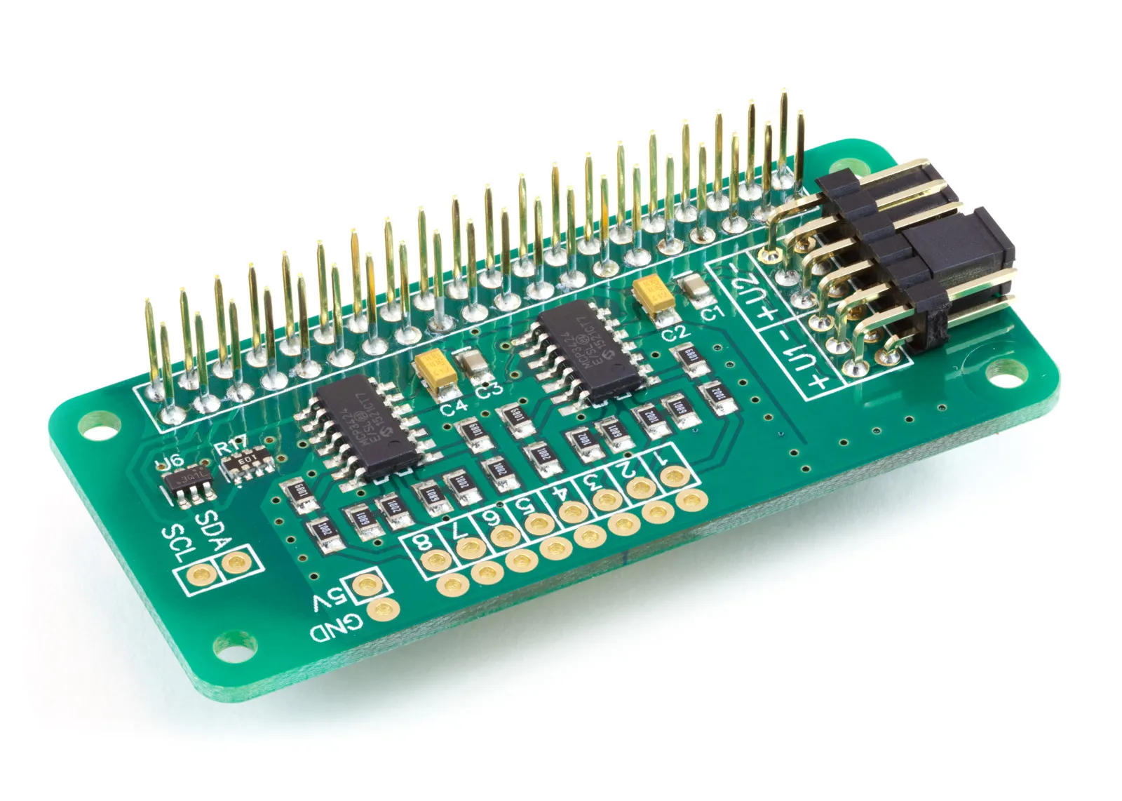
ADC Pi
8 Channel 17-bit Single-Ended Analogue to Digital Converter for the Raspberry Pi and Single-Board Computers
£17.99 ex VAT
In this tutorial we will use the ADC Pi to read the output of an ACS712 30 Amp current sensor and print the measured current to the console once every half-second. You will need your Raspberry Pi, an ADC Pi, an ACS712 30A sensor module, a 5V supply for the sensor, and the circuit whose current you want to measure.
The same code works with the 5A and 20A versions of the ACS712 with a single number changed, which we will cover in Stage 3.
What the ACS712 is
The ACS712 is a Hall-effect current sensor from Allegro MicroSystems. The current you want to measure passes through a low-resistance copper conductor inside the chip. That current produces a magnetic field, and a Hall sensor sitting next to the conductor turns the field into a voltage. The chip outputs that voltage on a single pin, referenced to ground, so you can feed it straight into an analogue input on the ADC Pi without any external amplifier.
A few figures from the ACS712 datasheet are worth knowing before we wire anything up:
- It measures AC or DC, in both directions. With no current flowing, the output sits at half the supply voltage. On a 5V supply that is 2.5V. Current in one direction pushes the output above 2.5V; current in the other direction pulls it below. This is why the code subtracts 2.5V before doing anything else.
- The output is ratiometric. The 2.5V zero point and the sensitivity both scale with the supply voltage. If your 5V rail is actually sitting at 4.95V, the zero point moves to 2.475V. We come back to this when calibrating.
- The current path is isolated from the output. The datasheet specifies a minimum of 2.4 kVRMS of isolation between the conductor carrying your measured current (pins 1–4) and the signal pins that connect to the Raspberry Pi (pins 5–8).
- The conductor resistance is 1.2 mΩ. The sensor adds very little resistance to the circuit it is measuring.
- Total output error is ±1.5% at 25°C, and the usable bandwidth is 80 kHz.
The sensitivity, or how many millivolts the output moves per amp, depends on which version you have:
| Version | Sensitivity | Range |
|---|---|---|
| ACS712-05B | 185 mV/A | ±5 A |
| ACS712-20A | 100 mV/A | ±20 A |
| ACS712-30A | 66 mV/A | ±30 A |
The lower-range parts are more sensitive, so they give a larger voltage swing per amp and resolve smaller currents.
Why use an ACS712 instead of a shunt resistor
The traditional way to measure current is a shunt: a small, accurate resistor placed in series with the load, where you measure the voltage across it and apply Ohm's law. It works, but it has two awkward properties that the ACS712 avoids.
The first is isolation. With a shunt, the points you measure sit at the same potential as the load. If the load is on a high-side or mains circuit, your measurement points are at that voltage too, which is both a safety problem and a wiring problem. You generally need a differential amplifier to lift the small shunt voltage away from the load potential before an ADC can read it. The ACS712 keeps the measured circuit electrically separate from the output by 2.4 kVRMS, so the side you connect to the Raspberry Pi stays at a safe, ground-referenced voltage.
The second is the measurement itself. A shunt produces a small differential voltage, often tens of millivolts, sitting on top of whatever voltage the load is at, so it needs amplifying and level-shifting before an ADC can use it. The ACS712 does that work internally and hands you a clean 0–5V signal referenced to ground, centred on 2.5V, which the ADC Pi reads directly. It also measures AC and DC and reports direction, which a bare shunt does not.
The trade-off is accuracy. A good shunt and instrumentation amplifier can beat the ACS712's ±1.5% total error and its noise floor, and the ACS712 will pick up strong external magnetic fields and drift slightly with temperature. For most monitoring, motor-current and load-detection work it is the easier and safer choice, but for laboratory-grade precision a shunt still has its place.
A note on voltage. The isolation rating lets the ACS712 sit in higher-voltage circuits, but if you are measuring anything connected to the mains, or any voltage high enough to cause harm, you should take all appropriate precautions to keep yourself and everyone else safe. If you are new to this, keep your experiments to low-voltage DC.
Before you start
We will use the AB Electronics Python library to talk to the ADC Pi. To download the library, visit our Python Library and Demos knowledge base article.
You must enable i2c on your Raspberry Pi; see our other tutorial: I2C, SMBus and Raspberry Pi.
The library uses python3-smbus, which you can install with apt-get:
sudo apt-get update
sudo apt-get install python3-smbus
With the library installed and i2c enabled, we can begin.
Stage 1 – Connecting the ACS712
If you haven't already, fit your ADC Pi onto the Raspberry Pi's GPIO header. Make sure the Raspberry Pi is turned off when you do this to minimise the risk of damaging either board.
The ACS712 module has two sides. One side is the current path: two screw terminals that you wire in series with the load, so the current you want to measure flows through the sensor on its way to the load. The other side is the signal connection, with three pins:
- VCC to a 5V pin on the Raspberry Pi.
- GND to a ground pin, shared with the Raspberry Pi.
- OUT to input channel 1 on the ADC Pi.
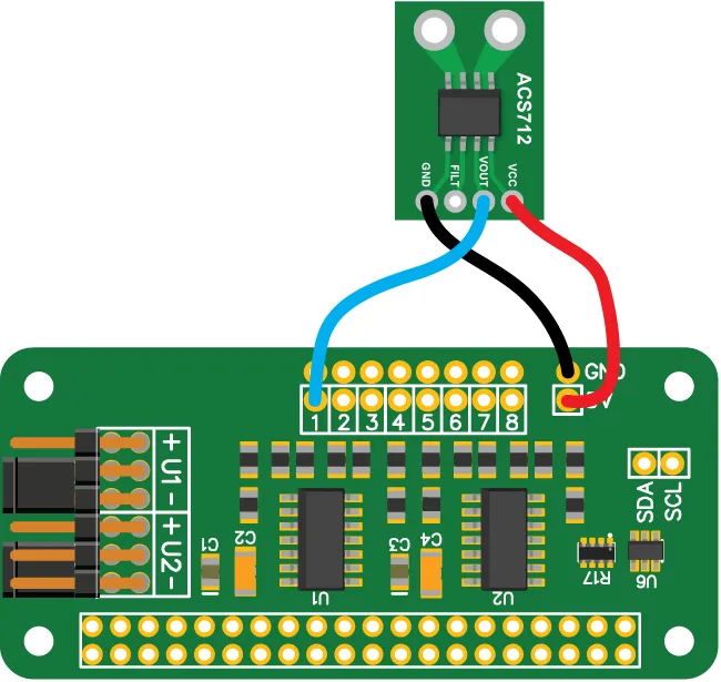
With no current flowing through the screw terminals, the OUT pin sits at 2.5V. The ADC Pi reads inputs in the 0 to 5V range, so the sensor's output sits comfortably within it: a 30A sensor swings roughly 0.52V to 4.48V across its full ±30A range, well inside what the ADC Pi can read.
Stage 2 – Writing the code
We will create a new Python file called demo_acs712_30.py. You can use your favourite text editor. A complete copy is in the ADCPi/demos/ folder of the Python library, and you can view it on our GitHub page.
At the top of the file we import the libraries we need. time lets us pause between readings, os lets us clear the console, and ADCPi is the library that talks to the board.
import time
import os

from ADCPi import ADCPi
Next we write a small function to turn a voltage reading into a current. This is where the sensor's behaviour from the first section turns into arithmetic.
def calc_current(value):
    return (value - 2.5) / 0.066
Two numbers are doing the work here. The 2.5 is the zero-current output: half of the 5V supply. Subtracting it gives us the signed voltage swing caused by current. Positive for one direction, negative for the other.
The 0.066 is the sensitivity of the 30A sensor, expressed in volts per amp. The datasheet quotes the 30A part as 66 mV/A, which is 0.066 V/A, the figure we divide by. Dividing the voltage swing by the sensitivity gives the current in amps.
Now the main function. We create an instance of the ADCPi class with the two i2c addresses for the board, 0x68 and 0x69, and set it to 18-bit resolution.
def main():

    adc = ADCPi(0x68, 0x69, 18)
A note on 18-bit mode and single-ended inputs
You will see the ADC Pi described as a 17-bit converter even though we set it to 18 bits here, and it is worth understanding why.
The ADC Pi uses the MCP3424, which is a differential converter. When you ask it for an 18-bit reading, the value it returns is signed: the most significant of the 18 bits is a sign bit that tells you which way round the two differential inputs are. The remaining 17 bits carry the magnitude.
The ADC Pi wires its inputs single-ended — each channel is measured against the board's ground reference rather than as a true differential pair. The input voltage is therefore always positive, the sign bit never changes, and it never carries any useful information. That leaves 17 bits of usable resolution, which is why the board is a 17-bit single-ended ADC even when the chip is running in its 18-bit mode.
One practical consequence: at 18-bit resolution the MCP3424 produces 3.75 readings per second. That is fine for displaying a DC current or a slowly-changing load, which is what this demo does. It is far too slow to capture the shape of a 50 or 60 Hz AC waveform. For that you would drop to a lower bit depth for a faster sample rate and calculate the RMS value yourself. This demo reports the instantaneous reading.
The reading loop
Back in main, we add a loop that clears the screen, reads channel 1, converts it to a current, prints it, and waits half a second before going round again.
    while True:

        os.system('clear')

        print("Current on channel 1: %02f" % calc_current(adc.read_voltage(1)))

        time.sleep(0.5)
adc.read_voltage(1) returns the voltage on channel 1 in volts, which we pass straight into calc_current. Finally we call main when the file is run directly.
if __name__ == "__main__":
    main()
The complete program looks like this:
import time
import os

from ADCPi import ADCPi


def calc_current(value):
    return (value - 2.5) / 0.066


def main():

    adc = ADCPi(0x68, 0x69, 18)  # ADC Pi at addresses 0x68 and 0x69, 18-bit mode

    while True:

        os.system('clear')  # clear the console

        # read channel 1, convert to current, and print
        print("Current on channel 1: %02f" % calc_current(adc.read_voltage(1)))

        time.sleep(0.5)  # wait half a second


if __name__ == "__main__":
    main()
Save the file and run it in a terminal with:
python3 demo_acs712_30.py
The screen will clear and show the current on channel 1, updating twice a second. With no load you should read close to zero; pass a current through the sensor and the figure will change, going negative if the current flows the other way through the terminals.
Stage 3 – Using the 5A and 20A sensors
The only thing that changes between the three versions of the ACS712 is the sensitivity, so switching sensors means changing one number. The cleaner way to do this is to pull the two constants out of the function so they are easy to find and edit:
SENSITIVITY = 0.066  # volts per amp: 0.185 (5A), 0.1 (20A), 0.066 (30A)
ZERO_POINT = 2.5     # half of the 5V supply

def calc_current(value):
    return (value - ZERO_POINT) / SENSITIVITY
To use a different sensor, set SENSITIVITY to match:
| Version | Sensitivity (datasheet) | Value to use |
|---|---|---|
| ACS712-05B (5A) | 185 mV/A | 0.185 |
| ACS712-20A (20A) | 100 mV/A | 0.1 |
| ACS712-30A (30A) | 66 mV/A | 0.066 |
Nothing else in the program needs to change. The 5A sensor gives the largest voltage swing per amp and so resolves the smallest currents; the 30A sensor covers the widest range at the cost of resolution.
Calibrating the zero point
The 2.5 zero point assumes a perfect 5V supply, but a Raspberry Pi's 5V rail is rarely exactly 5V, and because the ACS712 output is ratiometric, the zero point moves with it. If your readings sit slightly off zero with no current flowing, that is why.
To calibrate, leave the sensor with no current through it and read the raw voltage:
print(adc.read_voltage(1))
Use the value you see as your ZERO_POINT instead of 2.5. This removes the standing offset and gives you accurate readings around zero without changing anything else.
(images created with Fritzing)
Note: documents in Portable Document Format (PDF) require Adobe Acrobat Reader 5.0 or higher to view, download Adobe Acrobat Reader or other PDF reading software for your computer or mobile device.
Also useful for your Raspberry Pi project
Temperature & Sensing
1 Wire Pi Plus
Connect dozens of 1-Wire sensors - temperature, iButtons, EEPROMs - via a single GPIO pin. Stacks directly on the 40-pin header.
Analogue I/O
ADC Pi
Read up to 8 analogue inputs - perfect for pairing with your temperature sensors or other analogue-output devices.
All-in-one
Expander Pi
Combines ADC, DAC, 32 GPIO ports and a real-time clock on one board. The most versatile board for complex Raspberry Pi projects.
Chapters
Related Articles
Order these Boards
ADC Pi
8 Channel 17-bit Single-Ended Analogue to Digital Converter for the Raspberry Pi and Single-Board Computers
£17.99 ex VAT