The AB Electronics UK Knowledge Base provides support solutions, tutorials and troubleshooting guides.

YOU WILL NEED THIS BOARD
- What is the IO Pi Plus?
- How do I set up the IO Pi Plus?
- Can the IO Pi Plus generate PWM signals?
- What power supply requirements does the IO Pi Plus have?
- How do I handle I2C addressing conflicts or connection issues with the IO Pi Plus?
- Is there customer support available for troubleshooting or project guidance?
- Do you have tutorials for getting started with the IO Pi Plus?
- What programming languages can I use with the IO Pi Plus?
- Can the IO Pi Plus be used with systems other than Raspberry Pi?
- Does the IO Pi Plus support analogue inputs?
- How do I configure the address settings on the IO Pi Plus?
- Can the IO Pi Plus be used for interrupt-driven applications?
- Is there a maximum voltage and current rating for the IO Pi Plus pins?
- How do I ensure my IO Pi Plus board lasts long?
- Can I use the IO Pi Plus for home automation projects?
- What should I do if my IO Pi Plus is not recognised by the Raspberry Pi?
- What is the difference between the IO Pi Plus and the IO Zero 32?
- What connectors can I use with the IO Pi Plus
- Can I use the IO Pi Plus with Arduino
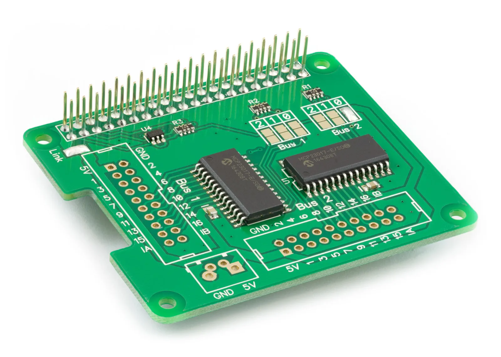
What is the IO Pi Plus?
The IO Pi Plus is a 32-channel GPIO development board designed to work with the Raspberry Pi and other compatible single-board computers. It utilises two MCP23017 16-bit I/O expanders to provide additional digital connections for various projects. Full technical details and address-options are available on the IO Pi Plus product page.
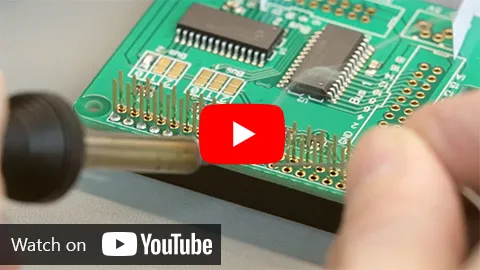
How do I set up the IO Pi Plus?
To get started with the IO Pi Plus, you need to solder the 40-pin GPIO connector onto the PCB. Watch our assembly guide on YouTube to see how to solder the connector and fit the IO Pi Plus onto a Raspberry Pi.
To control the IO Pi Plus you can use one of our various programming libraries. A range of programming languages are available, including Python, C, and Node.JS, which can be downloaded from the AB Electronics GitHub repository. There are also several tutorials available in our IO Pi Plus Knowledge Base, such as setting up interrupts and using the board with Home Assistant.
Can the IO Pi Plus generate PWM signals?
The IO Pi Plus is not capable of generating true PWM signals directly through its pins. The board's design allows toggling pins on and off but does not support high-frequency PWM necessary for certain applications. We recommend using a dedicated PWM output board like the Servo Pi Zero for tasks requiring precise PWM control.
What power supply requirements does the IO Pi Plus have?
The IO Pi Plus can be powered directly from the Raspberry Pi. You also have the option to power the MCP23017 IO controllers from an external 5V power supply. To use an external 5V supply remove the “Link” solder bridge to disconnect the Raspberry Pi’s 5V supply and connect your external power supply to the 5V and GND connections on the board.
The IO Pi Plus requires a 3.3V connection from the GPIO header for proper operation alongside a 5V supply if using the board externally from the Raspberry Pi. The 3.3V supply is required for the I2C to operate correctly. It is essential to ensure these voltages are stable and consistent to avoid damage to the Raspberry Pi or the development board.
How do I handle I2C addressing conflicts or connection issues with the IO Pi Plus?
For troubleshooting I2C addressing issues, first, ensure no other device is causing conflicts on the I2C bus. If you have two devices using the same I2C address you can change the address on the IO Pi Plus using the Address Select solder pads. A list of available I2C addresses can be found on the IO Pi Plus product page.
If connection problems persist, it might be necessary to inspect the solder joints on the IO Pi Plus or consider reflowing them to ensure a solid connection. Detailed steps on how to handle these and other troubleshooting tips can be found in the IO Pi Plus forums and support articles.
Is there customer support available for troubleshooting or project guidance?
AB Electronics offers an extensive IO Pi Plus Support Forum where users can post questions, share projects, and find solutions from both the community and the company's support team. This platform is a valuable resource for both new and experienced users working with the IO Pi Plus and other products from AB Electronics UK.
Do you have tutorials for getting started with the IO Pi Plus?
We have a range of tutorials available in our IO Pi Plus Knowledge Base to guide you in using the IO Pi Plus. Our tutorials cover the basics like connecting inputs and outputs as well as more complicated tasks including using the IO Pi Plus with the Home Assistant Operating System and connecting high-power devices using relays and opto-couplers.
What programming languages can I use with the IO Pi Plus?
We currently provide support for the IO Pi Plus with the following programming languages.
- Python
- MicroPython (Raspberry Pi Pico)
- C
- C++
- Node.JS
- .Net Core
- Arduino
- Home Assistant
Libraries and sample codes are available on the AB Electronics UK GitHub page for these languages.
Can the IO Pi Plus be used with systems other than Raspberry Pi?
Yes, the IO Pi Plus is compatible with various single-board computers like Orange Pi, Asus Tinker Board, and Odroid, if they support similar GPIO configurations and have I2C communication capabilities.
Does the IO Pi Plus support analogue inputs?
No, the IO Pi Plus is designed for digital input/output and does not have analogue input capabilities. For projects requiring analogue inputs, consider using a separate ADC (Analog to Digital Converter) development board like the ADC Pi from AB Electronics UK.
We have an Analogue to Digital converter buyers guide that can help you find the best ADC development board for your project.
How do I configure the address settings on the IO Pi Plus?
Address settings on the IO Pi Plus are configured using solder jumpers on the board. You can set up to eight unique addresses for the IO Pi Plus by configuring these jumpers, allowing multiple boards to be used on the same I2C bus without address conflicts.
The product page on our website for the IO Pi Plus has detailed instructions on changing the I2C address.
Can the IO Pi Plus be used for interrupt-driven applications?
Yes, the IO Pi Plus supports interrupt-driven applications. You can configure interrupts for inputs which allows you to respond to changes in input status without the need to continuously poll the input pins.
We have two tutorials in our Knowledge Base to help you build interrupt-driven applications.
Is there a maximum voltage and current rating for the IO Pi Plus pins?
Each I/O pin on the IO Pi Plus can handle a maximum current of 25 mA and a voltage from 0 to Vdd, which is typically 5V. The maximum current for a single I/O bus is 125 mA.
How do I ensure my IO Pi Plus board lasts long?
To ensure longevity, avoid exposing the IO Pi Plus to voltages above its rating, and be mindful of static electricity during installation. Do not exceed the current rating for the I/O pins or the overall rating for each I/O bus. Properly securing all connections and using a clean and stable power supply will also help in maintaining the board's health.
Can I use the IO Pi Plus for home automation projects?
The IO Pi Plus is an excellent choice for home automation projects, especially when used with the Home Assistant platform. You can control lights, sensors, and other home devices by integrating the IO Pi Plus into your Home Assistant setup.
What should I do if my IO Pi Plus is not recognised by the Raspberry Pi?
First, check your connections to ensure that everything is properly aligned and securely attached. Review the soldering on the GPIO connector, and make sure the I2C interface is enabled in the Raspberry Pi's configuration settings.
Our tutorial Enabling I2C on the Raspberry Pi guides you through the steps needed to use I2C on the Raspberry Pi.
If the issue persists, consult the support forums for additional troubleshooting steps.
What is the difference between the IO Pi Plus and the IO Zero 32?
The main differences between the IO Pi Plus and the IO Zero 32 from AB Electronics UK revolve around their design, features, and form factor, making them suitable for different types of projects and applications.
- Form Factor: The IO Pi Plus is designed with a larger form factor, fitting directly onto the larger Raspberry Pi models such as the Raspberry Pi 4 and 5. The IO Zero 32, on the other hand, has a smaller form factor intended for use with the Raspberry Pi Zero, making it more suitable for compact or embedded applications.
- Pin Expansion: Both models offer 32 digital I/O ports, but the pins are laid out differently due to their size differences, two bus connectors on the IO Pi Plus and one dual bus connector on the IO Zero 32. This impacts how they integrate with other hardware and peripherals in terms of physical layout and electrical interfacing.
- Pull-up Resistors: The IO Pi Plus contains internal 100K pull-up resistors on the inputs. The IO Zero 32 does not contain internal pull-up resistors so external resistors may be needed in some applications.
- Interrupts: The IO Pi Plus has comprehensive interrupt capabilities allowing you to set interrupt triggers on individual pins and with pre-programmed trigger events. The IO Zero 32 has basic interrupts that trigger when any input changes state.
What connectors can I use with the IO Pi Plus
The bus pins on the IO Pi Plus support a wide range of connectors. The holes are spaced 2.54mm apart in a grid of 10 x 2 pins.
The easiest way to connect external devices to the bus pins is using ribbon cables and IDC connectors. You will need two 20-contact IDC PCB headers soldered onto the IO Pi Plus. The right-angle header is best if you want to stack several hats on your Raspberry Pi as it allows the cables to plug into the side of the IO Pi Plus instead of on top.
You will also need two 20-way sockets and some 20-way ribbon cable
By using the IDC connectors and ribbon cable you have access to all the pins on the I/O bus, and you can easily disconnect the cable if needed. The ribbon cable can be split into individual cores to connect to external devices.
The 5V and GND pins can be used with 2.54mm or 5mm pitched screw terminals or other 2-pin connectors that use the same pitch spacing.
Can I use the IO Pi Plus with Arduino
Yes the IO Pi Plus can be used with the Arduino development boards. We have an Arduino library available in our GitHub repository. The easiest way to connect the IO Pi Plus to an Arduino is using our Arduino Uno to Raspberry Pi Adapter.
For more detailed guidance on each of these topics, tutorials, and troubleshooting tips, visiting the AB Electronics UK forums and our IO Pi Plus Knowledge Base is recommended.
If you also require analogue conversion, we recommend adding the ADC Pi rather than using only the IO Pi Plus.
Also useful for your Raspberry Pi project
Temperature & Sensing
1 Wire Pi Plus
Connect dozens of 1-Wire sensors - temperature, iButtons, EEPROMs - via a single GPIO pin. Stacks directly on the 40-pin header.
Analogue I/O
ADC Pi
Read up to 8 analogue inputs - perfect for pairing with your temperature sensors or other analogue-output devices.
All-in-one
Expander Pi
Combines ADC, DAC, 32 GPIO ports and a real-time clock on one board. The most versatile board for complex Raspberry Pi projects.
Chapters
- What is the IO Pi Plus?
- How do I set up the IO Pi Plus?
- Can the IO Pi Plus generate PWM signals?
- What power supply requirements does the IO Pi Plus have?
- How do I handle I2C addressing conflicts or connection issues with the IO Pi Plus?
- Is there customer support available for troubleshooting or project guidance?
- Do you have tutorials for getting started with the IO Pi Plus?
- What programming languages can I use with the IO Pi Plus?
- Can the IO Pi Plus be used with systems other than Raspberry Pi?
- Does the IO Pi Plus support analogue inputs?
- How do I configure the address settings on the IO Pi Plus?
- Can the IO Pi Plus be used for interrupt-driven applications?
- Is there a maximum voltage and current rating for the IO Pi Plus pins?
- How do I ensure my IO Pi Plus board lasts long?
- Can I use the IO Pi Plus for home automation projects?
- What should I do if my IO Pi Plus is not recognised by the Raspberry Pi?
- What is the difference between the IO Pi Plus and the IO Zero 32?
- What connectors can I use with the IO Pi Plus
- Can I use the IO Pi Plus with Arduino
Related Articles
- IO Pi Plus FAQ
- IO Pi Plus Tutorial 1 - The Blinking LED
- IO Pi Plus Tutorial 2 - Push the Button
- IO Pi Plus Tutorial 3 - Introducing Interrupts
- IO Pi Plus Tutorial 4 - More Interrupts
- IO Pi Plus Tutorial - MQTT Reading the Ports
- IO Pi Plus with Raspberry Pi Pico
- IO Pi Plus Tutorial - MQTT Control
- Driving Relays or Higher Loads with the IO Pi Plus
- Relay Board for the IO Pi Plus 2.1
- 16 Channel Opto-Isolated Input Board