The AB Electronics UK Knowledge Base provides support solutions, tutorials and troubleshooting guides.

YOU WILL NEED THIS BOARD
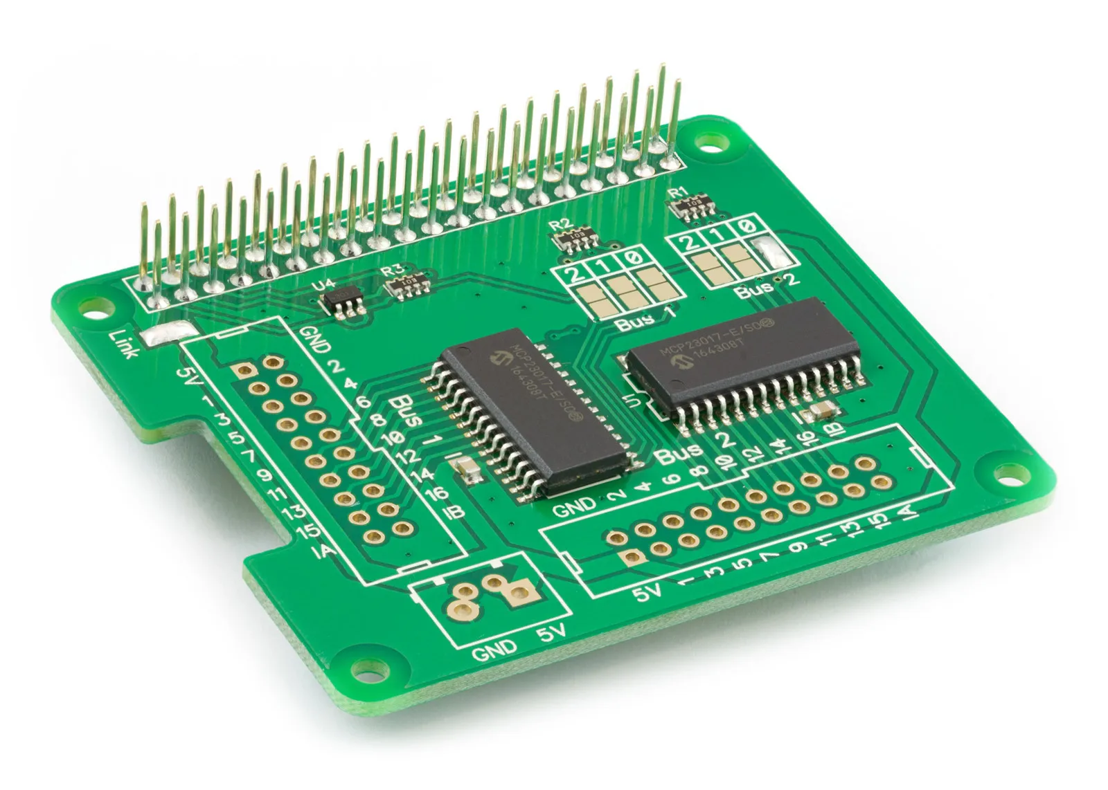
If you’re using a Raspberry Pi Pico and need more I/O pins, you can consider the IO Pi Plus board.
We have a MicroPython library to use with the Raspberry Pi Pico at our MicroPython Libraries GitHub Repository.
The example Python files can be found in /ABElectronics_MicroPython_Libraries/IOPi/demos/
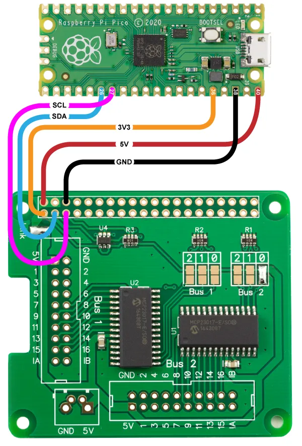
Connecting the IO Pi Plus to the Raspberry Pi Pico
The IO Pi Plus library uses the following pins on the Raspberry Pi Pico board.
| Pico Pin | Pico GPIO | Function | Pi Pin | Pi GPIO |
|---|---|---|---|---|
| 26 | 20 | I2C SDA | 3 | GPIO 2 |
| 27 | 21 | I2C SCL | 5 | GPIO 3 |
| 40 | VBUS | 5V | 2 | 5V Power |
| 38 | GND | GND | 6 | Ground |
| 36 | 3V3(OUT) | 3V3 | 1 | 3v3 Power |
Wiring Diagram:
Downloading and Installing the library
To download to your Raspberry Pi, type in the terminal:
git clone https://github.com/abelectronicsuk/ABElectronics_MicroPython_Libraries.git
To install the MicroPython Library, use the Thonny Python IDE.
Create a file for your chosen board and copy the contents of the Python file into that board's directory. For example, for the IO Pi Plus, create a new file in thonny called IOPi.py, copy contents from IOPi.py into the new file, and save it onto the Raspberry Pi Pico board.
Create a second file where your main program will reside and import the board library at the program's top.
from IOPi import IOPi
Run with "Run Current Command" or F5 in Thonny.
Classes:
IOPi(address, initialise, sda, scl)
Parameters:
address: i2c address for the target device. 0x20 to 0x27
initialise (optional): True = direction set as inputs, pull-ups disabled, ports not inverted. False = device state unaltered., defaults to True
sda (optional): I2C SDA pin. If no value is set, the class will default to pin 20.
scl (optional): I2C SCL pin. If no value is set, the class will default to pin 21.
Functions:
set_pin_direction(pin, value):
Sets the IO direction for an individual pin
Parameters:
pin: 1 to 16
value: 1 = input, 0 = output
Returns: null
get_pin_direction(pin)
Get the IO direction for an individual pin
Parameters:
pin: pin to read, 1 to 16
Returns: 1 = input, 0 = output
set_port_direction(port, value):
Sets the IO direction for the specified IO port
Parameters:
port: 0 = pins 1 to 8, 1 = pins 9 to 16
value: number between 0 and 255 or 0x00 and 0xFF. Each bit in the 8-bit number represents a pin on the port. 1 = input, 0 = output
Returns: null
get_port_direction(port):
Get the direction from an IO port
Parameters:
port: 0 = pins 1 to 8, 1 = pins 9 to 16
Returns: number between 0 and 255 (0xFF)
set_bus_direction(value):
Sets the IO direction for all pins on the bus
Parameters:
value: 16-bit number 0 to 65535 (0xFFFF). For each bit 1 = input, 0 = output
Returns: null
get_bus_direction()
Get the direction for an IO bus
Returns: 16-bit number 0 to 65535 (0xFFFF). For each bit 1 = input, 0 = output
set_pin_pullup(pin, value)
Set the internal 100K pull-up resistors for an individual pin
Parameters:
pin: pin to update, 1 to 16 value: 1 = enabled, 0 = disabled
Returns: null
get_pin_pullup(pin)
Get the internal 100K pull-up resistors for an individual pin
Parameters:
pin: pin to read, 1 to 16
Returns: 1 = enabled, 0 = disabled
set_port_pullups(port, value)
Set the internal 100K pull-up resistors for the selected IO port
Parameters:
port: 0 = pins 1 to 8, 1 = pins 9 to 16
value: number between 0 and 255 or 0x00 and 0xFF. Each bit in the 8-bit number represents a pin on the port. 1 = Enabled, 0 = Disabled
Returns: null
get_port_pullups(port):
Get the internal pull-up status for the selected IO port
Parameters:
port: 0 = pins 1 to 8, 1 = pins 9 to 16
Returns: number between 0 and 255 (0xFF)
set_bus_pullups(value)
Set internal 100K pull-up resistors for an IO bus
Parameters:
value: 16-bit number 0 to 65535 (0xFFFF). For each bit 1 = enabled, 0 = disabled
Returns: null
get_bus_pullups()
Get the internal 100K pull-up resistors for an IO bus
Returns: 16-bit number 0 to 65535 (0xFFFF). For each bit 1 = enabled, 0 = disabled
write_pin(pin, value)
Write to an individual pin 1 - 16
Parameters:
pin: 1 to 16
value: 1 = logic high, 0 = logic low
Returns: null
write_port(port, value)
Write to all pins on the selected port
Parameters:
port: 0 = pins 1 to 8, 1 = pins 9 to 16
value: number between 0 and 255 or 0x00 and 0xFF. Each bit in the 8-bit number represents a pin on the port. 1 = logic high, 0 = logic low
Returns: null
write_bus(value)
Write to all pins on the selected bus
Parameters:
value: 16-bit number 0 to 65535 (0xFFFF). For each bit 1 = logic high, 0 = logic low
Returns: null
read_pin(pin)
Read the value of an individual pin 1 - 16
Parameters:
pin: 1 to 16
Returns: 0 = logic low, 1 = logic high
read_port(port)
Read all pins on the selected port
Parameters:
port: 0 = pins 1 to 8, 1 = pins 9 to 16
Returns: number between 0 and 255 or 0x00 and 0xFF. Each bit in the 8-bit number represents a pin on the port. 0 = logic low, 1 = logic high
read_bus()
Read all pins on the bus.
Returns: 16-bit number 0 to 65535 (0xFFFF). Each bit in the 16-bit number represents a pin on the port. 0 = logic low, 1 = logic high
invert_pin(pin, value)
Invert the polarity of the selected pin
Parameters:
pin: 1 to 16
value: 0 = same logic state of the input pin, 1 = inverted logic state of the input pin
Returns: null
get_pin_polarity(pin)
Get the polarity of the selected pin
Parameters:
pin: pin to read, 1 to 16
Returns: 0 = same logic state of the input pin, 1 = inverted logic state of the input pin
invert_port(port, value)
Invert the polarity of the pins on a selected port
Parameters:
port: 0 = pins 1 to 8, 1 = pins 9 to 16
value: number between 0 and 255 or 0x00 and 0xFF. Each bit in the 8-bit number represents a pin on the port. 0 = same logic state of the input pin, 1 = inverted logic state of the input pin
Returns: null
get_port_polarity(port):
Get the polarity for the selected IO port
Parameters:
port: 0 = pins 1 to 8, 1 = pins 9 to 16
Returns: number between 0 and 255 (0xFF)
invert_bus(value)
Invert the polarity of the pins on the bus
Parameters:
value: 16-bit number 0 to 65535 (0xFFFF). For each bit, 0 = same logic state of the input pin, 1 = inverted logic state of the input pin
Returns: null
get_bus_polarity()
Get the polarity of the pins on the bus.
Returns: 16-bit number 0 to 65535 (0xFFFF). For each bit, 0 = same logic state of the input pin, 1 = inverted logic state of the input pin
mirror_interrupts(value)
Sets whether the interrupt pins INT A and INT B are independently connected to each port or internally connected together
Parameters:
value: 1 = The INT pins are internally connected, 0 = The INT pins are not connected. INT A is associated with PortA, and INT B is associated with PortB
Returns: null
set_interrupt_polarity(value)
Sets the polarity of the INT output pins
Parameters:
value: 0 = Active Low, 1 = Active High
Returns: null
get_interrupt_polarity()
Get the polarity of the INT output pins
Returns: 1 = Active-high. 0 = Active-low.
set_interrupt_type(port, value)
Sets the type of interrupt for each pin on the selected port
Parameters:
port: 0 = pins 1 to 8, 1 = pins 9 to 16
value: number between 0 and 255 or 0x00 and 0xFF. Each bit in the 8-bit number represents a pin on the port. 1 = interrupt is fired when the pin matches the default value, 0 = the interrupt is fired on state change
Returns: null
get_interrupt_type(port):
Get the type of interrupt for each pin on the selected port
Parameters:
port: 0 = pins 1 to 8, 1 = pins 9 to 16
Returns: number between 0 and 255 (0xFF)
For each bit, 1 = interrupt is fired when the pin matches the default value, and 0 = interrupt fires on state change.
set_interrupt_defaults(port, value)
These bits set the compare value for pins configured for interrupt-on-change on the selected port.
An interrupt occurs if the associated pin level is the opposite of the register bit.
Parameters:
port: 0 = pins 1 to 8, 1 = pins 9 to 16, value: compare value between 0 and 255 or 0x00 and 0xFF. Each bit in the 8-bit number represents a pin on the port.
Returns: null
get_interrupt_defaults(port):
Get the interrupt default value for each pin on the selected port
Parameters:
port: 0 = pins 1 to 8, 1 = pins 9 to 16
Returns: number between 0 and 255 (0xFF)
set_interrupt_on_pin(pin, value)
Enable interrupts for the selected pin
Parameters:
pin: 1 to 16
value: 0 = interrupt disabled, 1 = interrupt enabled
Returns: null
get_interrupt_on_pin(pin)
Gets whether the interrupt is enabled for the selected pin
Parameters:
pin: pin to read, 1 to 16
Returns: 1 = enabled, 0 = disabled
set_interrupt_on_port(port, value)
Enable interrupts for the pins on the selected port
Parameters:
port: 0 = pins 1 to 8, 1 = pins 9 to 16
value: number between 0 and 255 or 0x00 and 0xFF. Each bit in the 8-bit number represents a pin on the port.
Returns: null
get_interrupt_on_port(port):
Gets whether the interrupts are enabled for the selected port
Parameters:
port: 0 = pins 1 to 8, 1 = pins 9 to 16
Returns: number between 0 and 255 (0xFF). For each bit 1 = enabled, 0 = disabled
set_interrupt_on_bus(value)
Enable interrupts for the pins on the bus
Parameters:
value: 16-bit number 0 to 65535 (0xFFFF). For each bit 1 = enabled, 0 = disabled
Returns: null
get_interrupt_on_bus()
Gets whether the interrupts are enabled for the bus
Returns: 16-bit number 0 to 65535 (0xFFFF). For each bit 1 = enabled, 0 = disabled
read_interrupt_status(port)
Read the interrupt status for the pins on the selected port
Parameters:
port: 0 = pins 1 to 8, 1 = pins 9 to 16
Returns: number between 0 and 255 or 0x00 and 0xFF. Each bit in the 8-bit number represents a pin on the port. 1 = Enabled, 0 = Disabled
read_interrupt_capture(port)
Read the value from the selected port at the time of the last interrupt trigger
Parameters:
port: 0 = pins 1 to 8, 1 = pins 9 to 16
Returns: number between 0 and 255 or 0x00 and 0xFF. Each bit in the 8-bit number represents a pin on the port. 1 = Enabled, 0 = Disabled
reset_interrupts()
Set the interrupts A and B to 0
Parameters: null
Returns: null
Usage
To use the IO Pi library in your code, you must first import the library:
from IOPi import IOPi
Next, you must initialise the IO object with the I2C address of the I/O controller chip. The default addresses for the IO Pi Plus are 0x20 and 0x21:
bus1 = IOPI(0x20)
We will read the inputs 1 to 8 from bus 2, so set port 0 as inputs and enable the internal pull-up resistors
bus1.set_port_direction(0, 0xFF)
bus1.set_port_pullups(0, 0xFF)
You can now read pin 1 with the following:
print('Pin 1: ' + str(bus1.read_pin(1)))
Also useful for your Raspberry Pi project
Temperature & Sensing
1 Wire Pi Plus
Connect dozens of 1-Wire sensors - temperature, iButtons, EEPROMs - via a single GPIO pin. Stacks directly on the 40-pin header.
Analogue I/O
ADC Pi
Read up to 8 analogue inputs - perfect for pairing with your temperature sensors or other analogue-output devices.
All-in-one
Expander Pi
Combines ADC, DAC, 32 GPIO ports and a real-time clock on one board. The most versatile board for complex Raspberry Pi projects.
Chapters
Related Articles
- IO Pi Plus FAQ
- IO Pi Plus Tutorial 1 - The Blinking LED
- IO Pi Plus Tutorial 2 - Push the Button
- IO Pi Plus Tutorial 3 - Introducing Interrupts
- IO Pi Plus Tutorial 4 - More Interrupts
- IO Pi Plus Tutorial - MQTT Reading the Ports
- IO Pi Plus with Raspberry Pi Pico
- IO Pi Plus Tutorial - MQTT Control
- Driving Relays or Higher Loads with the IO Pi Plus
- Relay Board for the IO Pi Plus 2.1
- 16 Channel Opto-Isolated Input Board