The AB Electronics UK Knowledge Base provides support solutions, tutorials and troubleshooting guides.

YOU WILL NEED THIS BOARD
In this tutorial, we will read from the inputs on the digital IO device on your Expander Pi and display the status of the inputs on the console. You will need your Raspberry Pi, an Expander Pi and up to 16 single pole switches and connecting wires.
We will use the AB Electronics Python library to talk to the Expander Pi. To download the library, visit our Python Library and Demos knowledge base article.
You must enable i2c on your Raspberry Pi; see our other tutorial on i2c: I2C, SMBus and Raspbian Linux.
The AB Electronics Python library uses another library called python3-smbus; you can install it using apt-get with the following commands.
sudo apt-get update
sudo apt-get install python3-smbus
With the libraries installed and the Raspberry Pi configured to use i2c, we can begin building our project.
If you haven’t done so, install your Expander Pi onto the Raspberry Pi by connecting it to the GPIO header. Make sure your Raspberry Pi is turned off when you do this to minimise the risk of damaging the Raspberry Pi or the Expander Pi.
Next, connect your input switches to the IO ports and connect the output of each switch to ground.
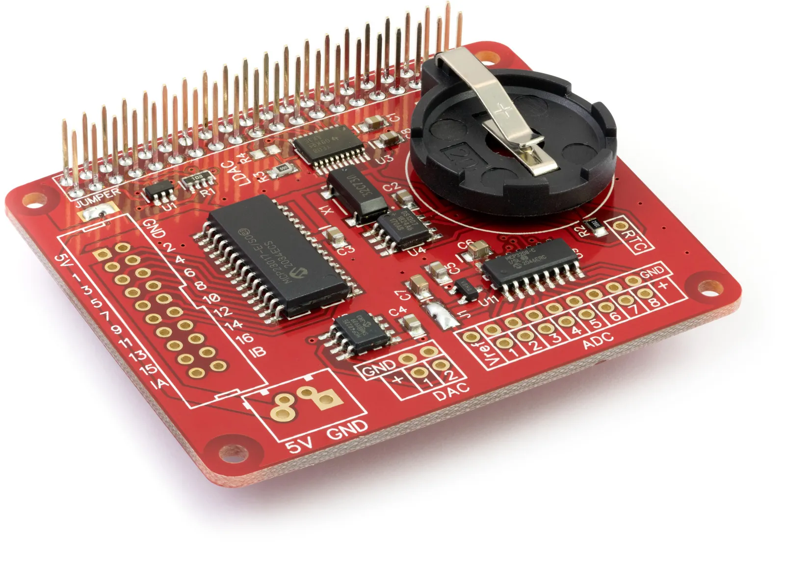
The Expander Pi contains an MCP23017 I/O controller chip from Microchip. The MCP23017 is an i2c-based controller having 16 I/O pins, which can be configured individually as inputs or outputs.
We will create a new Python program file called demo-ioread.py for this tutorial. You can use your favourite text editor to write the program. You can find a complete example of demo_ioread.py in the ABElectronics_Python_Libraries/ABElectronics_ExpanderPi/demos folder.
At the top of your program, you must import the IO class from the ExpanderPi and the time library.
#!/usr/bin/env python
import ExpanderPi
import time
The Expander Pi library is used for all communication with your Expander Pi; it gives you control over almost everything that can be done with the MCP23017 controller.
We will create an instance of the IO class and call it io.
io = ExpanderPi.IO()
With our new instance of the IO class, we can access all available methods for controlling the Expander Pi. Let’s begin by setting the pins to be input on pins 1 to 8.
io.set_port_direction(0, 0xFF)
The 16 channels on the I/O bus are split into two 8-pin ports. Port 0 controls pins 1 to 8, while port 1 controls pins 9 to 16. Having two 8-pin ports allows us to change the direction on 8 pins at once by sending an 8-bit byte of information to the Expander Pi. You can also set each pin separately using the set_pin_direction command, but for our tutorial today, we will use set_port_direction.
set_port_direction takes two variables; the first is the port you want to control, 0 for pins 1 to 8 and 1 for pins 9 to 16. The second variable is the command byte for setting the individual pin directions. Putting a pin to 0 makes it an output, while setting it to 1 makes it an input; remember, 0 = out, 1 = in.
As a byte in binary is 8 bits long, each bit represents one of the pins on the selected port. The least significant bit, or the one nearest the right, represents the lowest pin number, while the most significant bit or the one nearest the left, represents the highest pin number. If we wanted to set pins 1 to 4 as inputs and 5 to 8 as outputs, we could send the binary number 00001111. If we wished to pin 7 as an input and everything else as an output, we could send the binary number 01000000.
When working in Python or most other languages, it’s the standard convention when dealing with bytes to use hexadecimal rather than binary numbers, so 00001111 would become 0x0F while 01000000 becomes 0x40. If you are not very good at converting binary and hexadecimal in your head, we have an online converter you can use.
As we want all of the pins to be inputs, we will send the binary number 11111111, which is converted to hexadecimal is 0xFF.
Next, we need to set the internal pull-up resistors to be enabled. The pull-up resistors connect the input to the 5V supply using 100K resistors inside the IO chip. This will keep the inputs high, so when nothing is connected to the input, it will read 1. Connecting your switches between the inputs and ground will short the resistors to ground, pulling the input low. This means that turning the switch on will show a 0 on the input, while turning it off will show a 1.
io.set_port_pullups(0, 0xFF)
As with set_port_direction, set_port_pullups takes two variables: the port to write to 0 or 1 and the 8-bit value as detailed above.
We must repeat this for the second bus for pins 9 to 16.
io.set_port_direction(1, 0xFF)
io.set_port_pullups(1, 0xFF)
The Expander Pi is now set up to read the inputs.
We will first need a loop so that the same commands can run repeatedly. This can be done with a simple while loop.
while True:
As True is always true, the while loop will continue until you exit the program with a Ctrl-C.
We then need to clear the console.
os.system('clear')
Now, we read each of the IO input pins and write its status to the console.
    print 'Pin 1:  ' + str(io.read_pin(1))
    print 'Pin 2:  ' + str(io.read_pin(2))
    print 'Pin 3:  ' + str(io.read_pin(3))
    print 'Pin 4:  ' + str(io.read_pin(4))
    print 'Pin 5:  ' + str(io.read_pin(5))
    print 'Pin 6:  ' + str(io.read_pin(6))
    print 'Pin 7:  ' + str(io.read_pin(7))
    print 'Pin 8:  ' + str(io.read_pin(8))
    print 'Pin 9:  ' + str(io.read_pin(9))
    print 'Pin 10: ' + str(io.read_pin(10))
    print 'Pin 11: ' + str(io.read_pin(11))
    print 'Pin 12: ' + str(io.read_pin(12))
    print 'Pin 13: ' + str(io.read_pin(13))
    print 'Pin 14: ' + str(io.read_pin(14))
    print 'Pin 15: ' + str(io.read_pin(15))
    print 'Pin 16: ' + str(io.read_pin(16))
time.sleep takes one variable, a number representing the number of seconds to wait. 0.1 would wait for 100ms. This adds a short delay before rereading the inputs.
time.sleep(0.1)
That is everything we need to read the IO inputs.
#!/usr/bin/env python
import ExpanderPi
import time

io = ExpanderPi.IO()

# We will read the inputs 1 to 16 from the I/O bus so set port 0 and port 1 to be
# inputs and enable the internal pull-up resistors
io.set_port_direction(0, 0xFF)
io.set_port_pullups(0, 0xFF)

io.set_port_direction(1, 0xFF)
io.set_port_pullups(1, 0xFF)

while True:
    # clear the console
    os.system('clear')

    # read the pins 1 to 16 and print the results
    print('Pin 1:  ' + str(io.read_pin(1)))
    print('Pin 2:  ' + str(io.read_pin(2)))
    print('Pin 3:  ' + str(io.read_pin(3)))
    print('Pin 4:  ' + str(io.read_pin(4)))
    print('Pin 5:  ' + str(io.read_pin(5)))
    print('Pin 6:  ' + str(io.read_pin(6)))
    print('Pin 7:  ' + str(io.read_pin(7)))
    print('Pin 8:  ' + str(io.read_pin(8)))
    print('Pin 9:  ' + str(io.read_pin(9)))
    print('Pin 10: ' + str(io.read_pin(10)))
    print('Pin 11: ' + str(io.read_pin(11)))
    print('Pin 12: ' + str(io.read_pin(12)))
    print('Pin 13: ' + str(io.read_pin(13)))
    print('Pin 14: ' + str(io.read_pin(14)))
    print('Pin 15: ' + str(io.read_pin(15)))
    print('Pin 16: ' + str(io.read_pin(16)))

    # wait 0.5 seconds before reading the pins again
    time.sleep(0.1)
Save your program and run it in a command terminal using
python3 demo_ioread.py
You will be shown a list of the 16 inputs and their current state in the console window, with 1 being high or on and 0 being low or off.
Also useful for your Raspberry Pi project
Temperature & Sensing
1 Wire Pi Plus
Connect dozens of 1-Wire sensors - temperature, iButtons, EEPROMs - via a single GPIO pin. Stacks directly on the 40-pin header.
Analogue I/O
ADC Pi
Read up to 8 analogue inputs - perfect for pairing with your temperature sensors or other analogue-output devices.
All-in-one
Expander Pi
Combines ADC, DAC, 32 GPIO ports and a real-time clock on one board. The most versatile board for complex Raspberry Pi projects.