The AB Electronics UK Knowledge Base provides support solutions, tutorials and troubleshooting guides.

This product has been replaced with the 1 Wire Pi Plus Version 2.0.
Features
- 1-Wire® to I2C host interface with ESD protection diode.
- Stackable with other Raspberry Pi accessory boards.
- Buffered 5V I2C port.
- External 5V power input for the 1-Wire® interface.
- I2C address selection via solder jumpers.
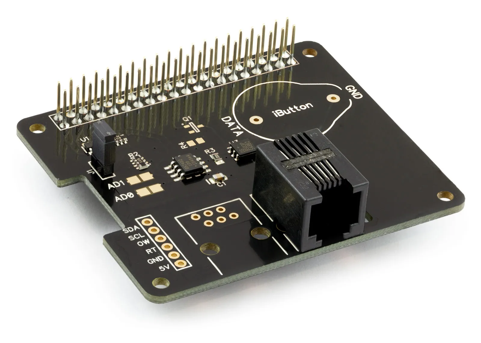
The 1 Wire Pi Plus from AB Electronics UK is a communication board supporting the 1-Wire® protocol designed for use on the Raspberry Pi. A 5V buffered I2C port is also provided on the board. Using our mounting kit pack, the 1 Wire Pi Plus can securely fit to your Raspberry Pi.
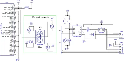
The 1-Wire® port on the 1 Wire Pi Plus is based around a DS2482-100 I2C to 1-Wire® bridge device. The DS2482-100 provides bi-directional protocol conversion between the I2C port on the Raspberry Pi and any attached 1-Wire® devices. An ESD Protection Diode protects the 1 Wire Pi Plus and Raspberry Pi from electrostatic spikes on the 1-Wire® port. Connections to the 1-Wire® port can be made through the RJ-12 socket or the solder points on the PCB. We have a knowledge base article for configuring and using the 1-Wire® port on your Raspberry Pi.
The 1 Wire Pi Plus is powered through the host Raspberry Pi using the GPIO port, and extended pins on the GPIO connector allow you to stack the 1 Wire Pi Plus along with other development boards.
A 5V input port allows you to use an external power supply on the 1-Wire® interface, reducing the load on the Raspberry Pi. If you use the external 5V input, please remove the jumper on the board to isolate the Raspberry Pi 5V bus.
I2C Address Selection
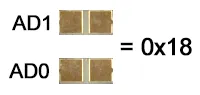
The 1 Wire Pi Plus includes two address selection solder jumpers which can be bridged with solder to give you up to 4 different I2C addresses.
Configuration 1:
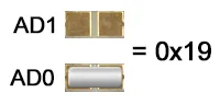
Configuration 2:
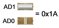
Configuration 3:
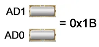
Configuration 4:
Datasheets
Compatibility Chart
| Model | Status |
|---|---|
| Raspberry Pi Model A | No |
| Raspberry Pi Model B | No |
| Raspberry Pi 1 Model A+ | Yes |
| Raspberry Pi 1 Model B+ | Yes |
| Raspberry Pi 2 Model B | Yes |
| Raspberry Pi 3 Model B | Yes |
| Raspberry Pi Zero | Yes |
| Raspberry Pi Zero W | Yes |
| Orange Pi | Yes |
| Asus Tinker Board | Yes |
| Odroid | Yes |
Input Ratings & Specifications
Vdd (5V input pin): 5.0V
Maximum current on 1-Wire pins: ±20 mA
I2C SDA/SCL voltage: 5.0 V
I2C port current: 100 mA
Schematic
Assembly Instructions
The 1 Wire Pi Plus is supplied with the 40-pin GPIO connector, RJ12 connector, and 2-pin jumper unsoldered.
Before using the 1 Wire Pi Plus, you must solder all three connectors onto the PCB. We suggest soldering the 40-pin GPIO connector first, the RJ12 connector, and the jumper. The RJ12 connector is supplied and clipped onto the PCB, and the PCB is pre-soldered on each pin. Solder the RJ12 connector by heating each pin until the solder melts, joining the pin to the pad below.
PCB Header Assembly Jig
Download and print our PCB Header Assembly Jig to hold your circuit board when soldering the header pins.
Connecting to the 1-Wire® Port
The 1-Wire® port on the 1-Wire Pi can be accessed through the female RJ12 socket or the solder points on the PCB. An ESD protection diode is fitted between the RJ12 port and the 1-Wire® interface IC.
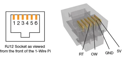
The pinout connections for the RJ12 port are shown below:
Pin Usage
1 5V
2 Ground
3 OW (1-Wire® Data, ESD Protected)
4 RT (1-Wire® Return/Ground, ESD Protected)
5 NC
6 NC
Mechanical Drawings
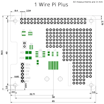
Click the image to enlarge
Sample Code
Note: documents in Portable Document Format (PDF) require Adobe Acrobat Reader 5.0 or higher to view, download Adobe Acrobat Reader or other PDF reading software for your computer or mobile device.

Related Products
1 Wire Pi Plus
1 Wire interface development board for the Raspberry Pi and Single-Board Computers
£9.59 ex VAT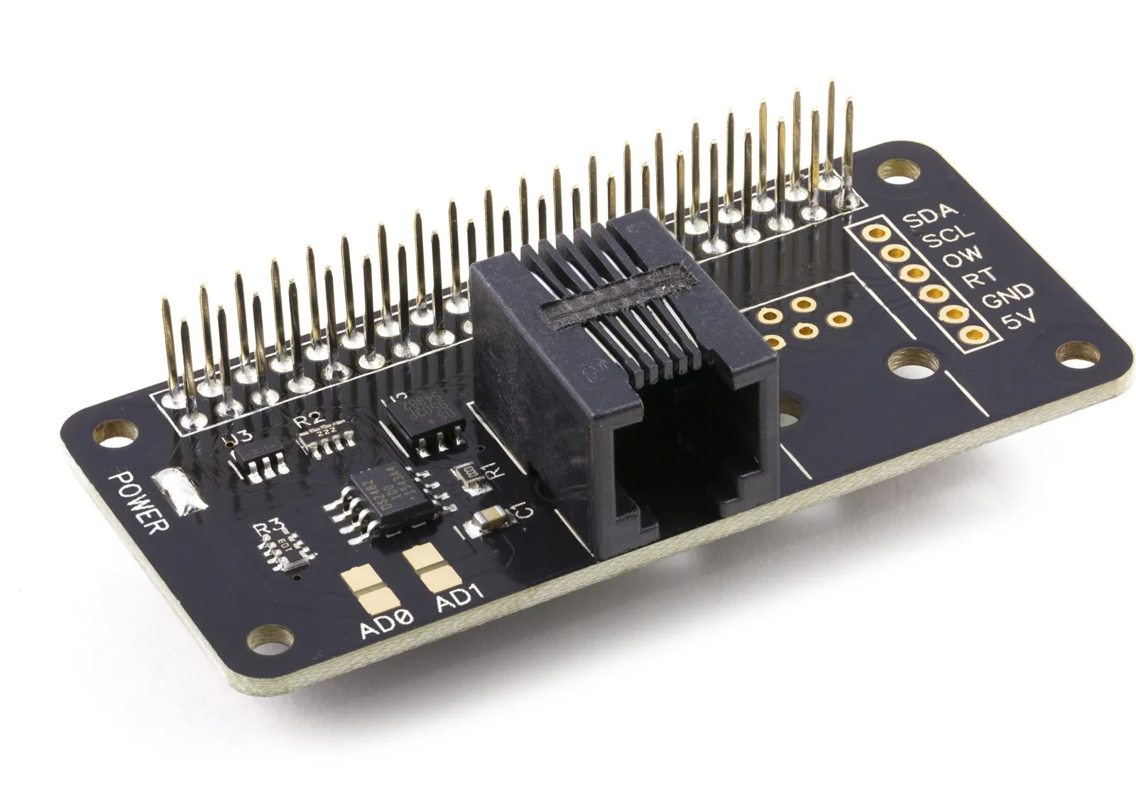
1 Wire Pi Zero
1 Wire interface development board for the Raspberry Pi Zero and Single-Board Computers
£9.19 ex VAT