The AB Electronics UK Knowledge Base provides support solutions, tutorials and troubleshooting guides.

YOU WILL NEED THIS BOARD
The IO Pi Plus version 1.0 has been updated to a new 2.1 version which you can purchase from our online shop.
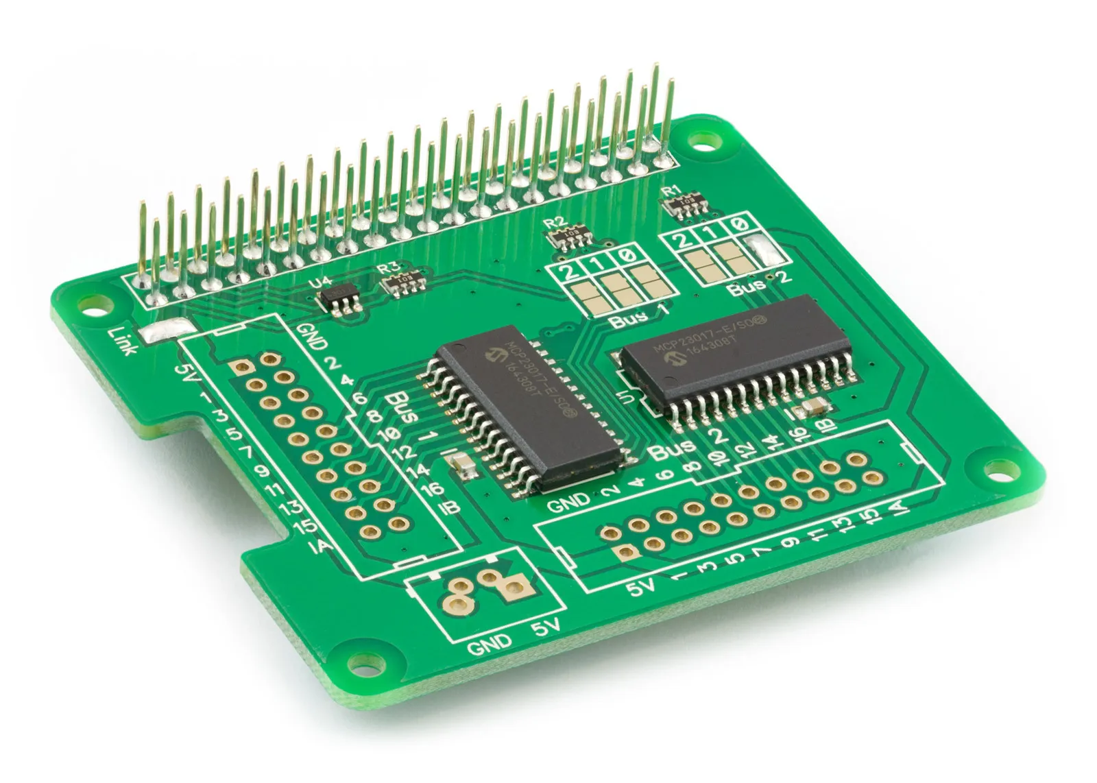
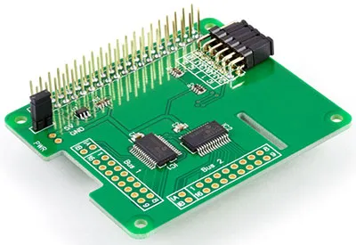
The IO Pi Plus is a 32-channel digital development board designed for use on the Raspberry Pi. The board is based around the MCP23017 16-bit I/O expander from Microchip Technology Inc. A pair of MCP23017 expanders are included on the board, allowing you to connect up to 32 digital inputs or outputs to the Raspberry Pi. The IO Pi Plus Expander is powered through the host Raspberry Pi using the GPIO port, and extended pins on the GPIO connector allow you to stack the IO Pi Plus along with other development boards.
The I2C address bits are selectable using the onboard jumpers. The MCP23017 supports up to 8 different I2C addresses, so with two MCP23017 devices on each IO Pi, you can stack up to 4 IO Pi boards on a single Raspberry Pi, giving a maximum of 128 I/O ports.
The IO Pi includes a 5V port that can be isolated from the Raspberry Pi via an isolation jumper. You can use a separate high-current power supply to power the IO Pi, reducing the load on the Raspberry Pi. The use of an external supply is recommended if you plan on connecting more than one IO Pi to your Raspberry Pi.
I2C Address Selection
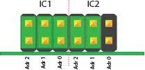
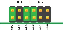
The MCP23017 contains three address select pins, which can be tied to Vss, Vdd. This gives 8 possible I2C addresses for each chip. The IO Pi includes two MCP23017 chips, so you can stack up to 4 IO Pi boards on a single Raspberry Pi. To simplify address selection on the IO Pi, we have included a set of address selection pins which can be configured using the included jumpers. The illustrations below show the four recommended configurations for your IO Pi and the associated I2C addresses.
Note:
Disconnect the IO Pi from the Raspberry Pi before changing the address pins. The address pins are tied to Vdd (high) via a 10K resistor, so the jumper connects a pin to ground (low).
Default Configuration (IC1 = 0x20, IC2 = 0x21)
When you purchase the IO Pi, the address selection jumpers will be pre-configured to the following addresses. IC1 Port = I2C Address: 0x20, IC2 Port = I2C Address: 0x21
Recommended Address Configurations
Configuration 1:
IC1 Port = I2C Address: 0x20
IC2 Port = I2C Address: 0x21
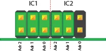
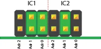
Configuration 2:
IC1 Port = I2C Address: 0x22
IC2 Port = I2C Address: 0x23
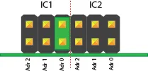
Configuration 3:
IC1 Port = I2C Address: 0x24
IC2 Port = I2C Address: 0x25
Configuration 4:
IC1 Port = I2C Address: 0x26
IC2 Port = I2C Address: 0x27
Compatibility Chart
| Model | Status |
|---|---|
| Raspberry Pi Model A | No |
| Raspberry Pi Model B | No |
| Raspberry Pi 1 Model A+ | Yes |
| Raspberry Pi 1 Model B+ | Yes |
| Raspberry Pi 2 Model B | Yes |
| Raspberry Pi 3 Model B | Yes |
| Raspberry Pi Zero | Yes |
| ODroid C1 | Yes |
| ODroid C2 | Yes |
Features
- 32 Digital Inputs/Outputs
- Control via the Raspberry Pi I2C port
- Stack up to 4 IO Pi boards on a single Raspberry Pi
- Jumper selectable I2C addresses
- External 5V Input with isolation jumper
- Based on the MCP23017 from Microchip Technologies Inc
- Configurable interrupt output pins - Configurable as active-high, active-low or open-drain
- INTA and INTB can be configured to operate independently or together
- Configurable interrupt source - Interrupt-on-change from configured register defaults or pin changes
- Polarity Inversion register to configure the polarity of the input port data
Input Ratings & Specifications
Vdd (5V input pin when isolation jumper is removed): 4.5V - 5.5V
All digital inputs and outputs: 0 - Vdd
Current at I/O Pin (sourced or sunk): 25 mA
Maximum current on a single I/O Bank (1 MCP23017 device): 125 mA
Assembly Instructions
The IO Pi Plus is supplied with the 40-pin GPIO connector, power jumper, and the unsoldered 12-pin address connector.
Before using the IO Pi Plus, you must solder both connectors onto the PCB. We suggest soldering the 40-pin GPIO connector first, then the address select connector, and then the power jumper.
PCB Header Assembly Jig
Download and print our PCB Header Assembly Jig to hold your circuit board when soldering the header pins.
![]()
Installation
To install the IO Pi, press the 40-pin connector down onto the Raspberry Pi GPIO pins with the board sitting over the top of the Raspberry Pi.
If installing more than one IO Pi on a single Raspberry Pi board, you must configure the address select jumpers for each IO Pi.
Remove the isolation jumper when connecting an external power supply to the 5V port.
Schematic
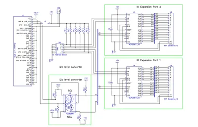
Click to download the schematic PDF.
Mechanical Drawings
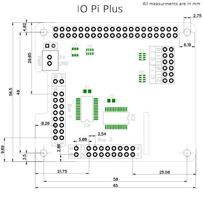
Click the image to enlarge
Sample Code
Arduino, C, Windows 10 IOT, and Python libraries are available for this development board. You can download all of the libraries from GitHub at:
GitHub AB Electronics UK Repository
Download the Arduino libraries from: Arduino Libraries GitHub Repository
To download the C libraries to your Raspberry Pi, type in the terminal:
git clone https://github.com/abelectronicsuk/ABElectronics_C_Libraries.git
To download the Python libraries to your Raspberry Pi, type in the terminal:
git clone https://github.com/abelectronicsuk/ABElectronics_Python_Libraries.git
Download the Windows 10 IOT libraries from: GitHub Windows 10 IOT


Tutorials
Our Knowledge Base has several tutorials for the IO Pi Zero and IO Pi Plus.
IO Pi Tutorials
Legacy IO Pi Versions
Note: documents in Portable Document Format (PDF) require Adobe Acrobat Reader 5.0 or higher to view, download Adobe Acrobat Reader or other PDF reading software for your computer or mobile device.
Also useful for your Raspberry Pi project
Temperature & Sensing
1 Wire Pi Plus
Connect dozens of 1-Wire sensors - temperature, iButtons, EEPROMs - via a single GPIO pin. Stacks directly on the 40-pin header.
Analogue I/O
ADC Pi
Read up to 8 analogue inputs - perfect for pairing with your temperature sensors or other analogue-output devices.
All-in-one
Expander Pi
Combines ADC, DAC, 32 GPIO ports and a real-time clock on one board. The most versatile board for complex Raspberry Pi projects.
Related Articles
- Delta-Sigma Pi (Discontinued)
- IO Pi (Discontinued)
- ADC Pi (Discontinued)
- Serial Pi (Discontinued)
- Expander Pi (Discontinued)
- Logic Level Converter (Discontinued)
- RTC Pi (Discontinued)
- ADC DAC Pi (Discontinued)
- Buffer Pi - Legacy Product
- RTC Alarm Pi (Discontinued)
- Com Pi (Discontinued)
- IO Pi Plus 1.0 (Discontinued)
- IO Pi Zero (Discontinued)
- 1 Wire Pi (Discontinued)
- 1 Wire Pi Plus 1.0 (Discontinued)