The AB Electronics UK Knowledge Base provides support solutions, tutorials and troubleshooting guides.

YOU WILL NEED THIS BOARD
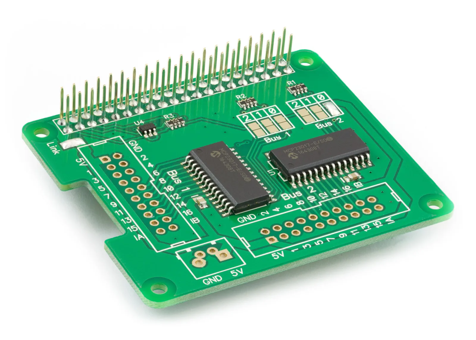
We often receive requests for a relay board to work with our IO Pi Plus development board. Developing and selling a relay board is something we have looked at several times in the past, but the problem we have found is making something that fits everyone’s needs. Relays come in a wide range of voltages, and while one person may need a board that works at 5V, another will need it to work at 24V. We would need to build and sell several different models to make boards suitable for everyone.
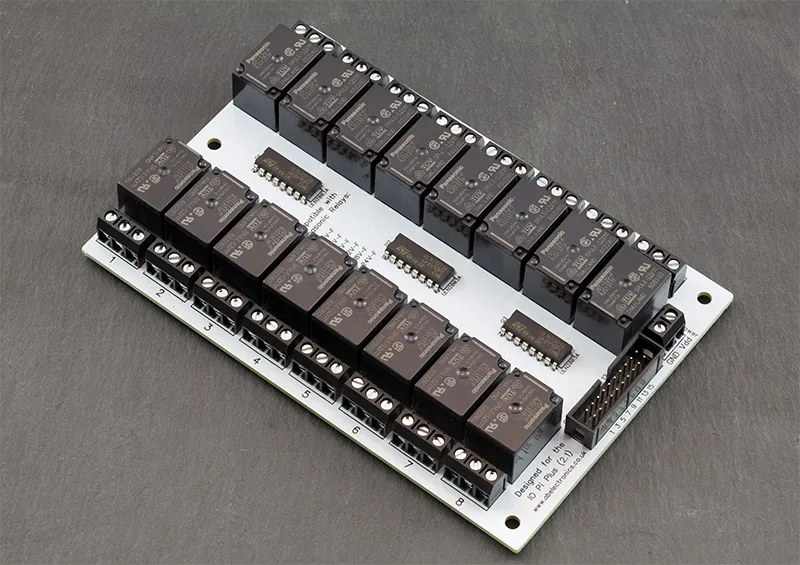
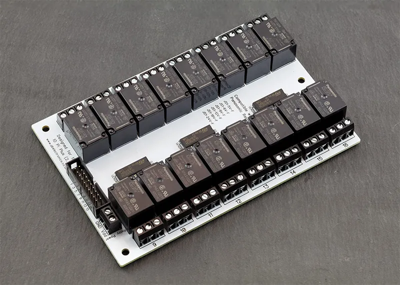
After thinking about the problem for a while, we have devised a simple solution. To go with the launch of the latest revision of our IO Pi Plus, we have designed a 16-channel relay board. We are giving away the design schematics and PCB files free of charge using the MIT license so you can build your own relay board using the supplied Gerber files or modify the schematic and PCB files to suit your needs. By offering the board this way, you can source the components and PCB from your favourite suppliers and build as many relay boards as you need for your project.
The 16-channel relay board is suitable for use with the IO Pi Plus version 2.1, which went on sale in February 2017. The board is compatible with the Panasonic JS series of single pole double throw relays and will work with relay coil voltages from 5V to 24V.
The relay board is compatible with the following relays:
JS1-5V-F
JS1-6V-F
JS1-9V-F
JS1-12V-F
JS1-18V-F
JS1-24V-F
To build the relay board, you will need the following parts:
16 x Panasonic JS series relays (model numbers listed above)
3 x ULN2003A (16-pin DIP package)
1 x 20 pin IDC PCB connector (2.54mm pitch)
16 x 3 pin 5mm screw terminals or other compatible connectors. (5.08mm will also work)
The 20-pin IDC connector uses the same pin configuration as the IO Pi Plus 2.1, so you can connect the two using two 20-pin IDC connectors and a ribbon cable. The relay numbers match the pin numbering on the IO Pi Plus bus, making it easy to control the relays using our IO Pi software libraries.
To power the relay coils, you will need a separate power supply that matches the voltage of the chosen relays. ULN2003A Darlington arrays switch the relays from a low-voltage logic input.
The PCB dimensions are 100mm x 150mm. Gerber files are included in the project folder and use a file name format compatible with several PCB manufacturers, including JLC PCB and Elecrow. The “Gerber Files.zip” file contains a zip of the Gerber files that can be uploaded directly to the PCB manufacturer of your choice.
Download the Gerber files from GitHub.
The schematic and PCB files are included in DipTrace format; you can download a free version of DipTrace from the Diptrace website/.
Note: The relay board can be used with older versions of the IO Pi Plus, IO Pi Zero and original IO Pi, but you will need only to connect the 16 control pins on the IDC connector. The ground pin must be connected separately to the GND pin on the IO Pi board, as earlier models did not include the ground on the IDC header.
Also useful for your Raspberry Pi project
Temperature & Sensing
1 Wire Pi Plus
Connect dozens of 1-Wire sensors - temperature, iButtons, EEPROMs - via a single GPIO pin. Stacks directly on the 40-pin header.
Analogue I/O
ADC Pi
Read up to 8 analogue inputs - perfect for pairing with your temperature sensors or other analogue-output devices.
All-in-one
Expander Pi
Combines ADC, DAC, 32 GPIO ports and a real-time clock on one board. The most versatile board for complex Raspberry Pi projects.
Related Articles
- IO Pi Plus FAQ
- IO Pi Plus Tutorial 1 - The Blinking LED
- IO Pi Plus Tutorial 2 - Push the Button
- IO Pi Plus Tutorial 3 - Introducing Interrupts
- IO Pi Plus Tutorial 4 - More Interrupts
- IO Pi Plus Tutorial - MQTT Reading the Ports
- IO Pi Plus with Raspberry Pi Pico
- IO Pi Plus Tutorial - MQTT Control
- Driving Relays or Higher Loads with the IO Pi Plus
- Relay Board for the IO Pi Plus 2.1
- 16 Channel Opto-Isolated Input Board