The AB Electronics UK Knowledge Base provides support solutions, tutorials and troubleshooting guides.

YOU WILL NEED THIS BOARD
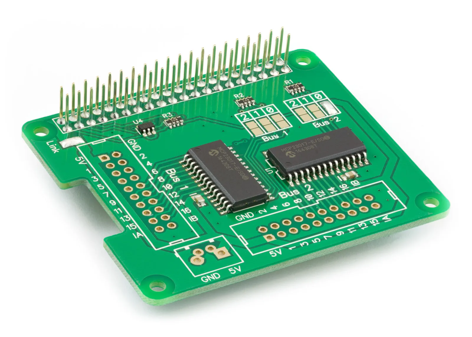
This tutorial will use MQTT (Message Queue Telemetry Transport) to communicate with an IO Pi Plus using the pins as outputs to switch on and off remotely. For this, you will need your Raspberry Pi and an IO Pi. You will also need a second computer as the server/host device.
We will use the AB Electronics Python library to talk to the IO Pi. To download the library, visit our Python Library and Demos knowledge base article.
You must enable i2c on your Raspberry Pi; see our other tutorial on i2c: I2C, SMBus and Raspbian Linux.
The AB Electronics Python library uses another library called python3-smbus; you can install it using apt-get with the following commands.
sudo apt-get update
sudo apt-get install python3-smbus
To install the required MQTT software, you need to install Mosquitto.
sudo apt-get install mosquitto
You also need to install the Python library paho-mqtt.
sudo apt-get install python3-paho-mqtt
We can now build our project with the libraries installed and the Raspberry Pi configured to use i2c.
Stage 1 – Create the client on the Raspberry Pi to listen and process the MQTT messages.
If you haven't done so, install your IO Pi onto the Raspberry Pi by connecting it to the GPIO header. Make sure your Raspberry Pi is turned off when you do this to minimise the risk of damaging the Raspberry Pi or the IO Pi.
The maximum current you can draw from any of the pins on the MCP23017 is 25mA, so we limit the current to a safe level by using the 200R resistor in series with the LED.
We will create a new Python program file for this tutorial called demo_mqtt_client.py. You can use your favourite text editor to write the program. You can find a complete example of demo_mqtt_client.py in the ABElectronics_Python_Libraries/IOPi/ folder.
At the top of your program, you will need to import the required libraries.
#!/usr/bin/env python
from IOPi import IOPi
import time
import paho.mqtt.client as mqtt
The IOPI library is used for all communication with your IO Pi; it gives you control over almost everything that can be done with the MCP23017 controller.
We will use both MCP23017 controllers and create two instances of the IOPI class.
iobus = IOPi(0x20)
iobusb = IOPi(0x21)
0x20 is the I2C address for the controller chip on bus 1, and 0x21 is the I2C address for the controller chip on bus 2; if you have changed the address selection jumpers on your IO Pi, then you will need to change this number to match the new address.
With our new instances of the IOPI class, we can access all available methods for controlling the IO Pi. Set all pins as outputs and set them to off.
iobus.set_port_direction(0, 0x00)
iobus.write_port(0, 0x00)

iobus.set_port_direction(1, 0x00)
iobus.write_port(1, 0x00)

iobusb.set_port_direction(0, 0x00)
iobusb.write_port(0, 0x00)

iobusb.set_port_direction(1, 0x00)
iobusb.write_port(1, 0x00)
Next, we will add the methods for the MQTT client.
def on_connect(client, userdata, flags, reason_code, properties):
    print(f"Connected: {reason_code}")
  client.subscribe("topic/iopi")
Now add the on_message function, which listens for a new message and splits the command into the pin and mode. This will turn the selected pin on the IO Pi buses on or off.
def on_message(client, userdata, msg):
  p,s = msg.payload.decode().split(",")
  if (int(p) <= 16):
    print("IO Bus 0 Pin: " + p)
    print("IO Bus 0 mode: " + s)
    iobus.write_pin(int(p), int(s))
  else:
    print("IO Bus 1 Pin: " + p)
    print("IO Bus 1 mode: " + s)
    iobusb.write_pin((int(p) -16), int(s))
Next, we add the connection code for MQTT to connect to the broker/server. Change the IP address to match your broker/server's address.
client = mqtt.Client(callback_api_version=mqtt.CallbackAPIVersion.VERSION2)
client.connect("10.0.0.49",1883,60)

client.on_connect = on_connect
client.on_message = on_message
client.loop_forever()
The IO Pi is now ready to listen for MQTT messages sent to "topic/iopi"
To run this code and set your Raspberry Pi to respond to MQTT messages, you need to run the script using the following:
python3 demo_mqtt_client.py
Stage 2 – Create the server/broker on the Raspberry Pi or other Linux computer to send and process the MQTT messages.
To send messages to the Raspberry Pi client, you need a server computer running the same software as the client machine.
We used an installation of Ubuntu for the following code, but any MQTT server/broker will perform the same function.
To install the required MQTT software, you need to install Mosquitto.
sudo apt-get install mosquitto
You also need to install the Python library paho-mqtt using pip3.
sudo apt-get install python3-pip
Now you can install paho-mqtt.
sudo pip3 install paho-mqtt
Once all the software has been installed, reboot the system, and we will create a new file called demo_mqtt_server.py to send MQTT messages to the Raspberry Pi.
The simple script will use commands to turn a pin on or off using client "topic/iopi" with the pin number and state message. For example, (5,1) turns on pin 5 on the second bus on the IO Pi Plus.
#!/usr/bin/env python3
import paho.mqtt.client as mqtt
import time

# Create client instance and connect to localhost
client = mqtt.Client(callback_api_version=mqtt.CallbackAPIVersion.VERSION2)
client.connect("localhost",1883,60)

# Publish message to topic/iopi and set pin 1 on bus 1 to on
client.publish("topic/iopi", "1,1");
time.sleep(2)

# Publish message to topic/iopi and set pin 1 on bus 1 to off
client.publish("topic/iopi", "1,0");
time.sleep(2)
# Publish message to topic/iopi and set pin 1 on bus 2 to on
client.publish("topic/iopi", "17,1");
time.sleep(2)
# Publish message to topic/iopi and set pin 1 on bus 2 to off
client.publish("topic/iopi", "17,0");
client.disconnect();
When you run this code, it will turn on pin 1 on bus 1 for two seconds, then turn the pin off, repeat using pin 1 on bus 2 (pin 17), and turn it off two seconds later.
python3 demo_mqtt_server.py
Also useful for your Raspberry Pi project
Temperature & Sensing
1 Wire Pi Plus
Connect dozens of 1-Wire sensors - temperature, iButtons, EEPROMs - via a single GPIO pin. Stacks directly on the 40-pin header.
Analogue I/O
ADC Pi
Read up to 8 analogue inputs - perfect for pairing with your temperature sensors or other analogue-output devices.
All-in-one
Expander Pi
Combines ADC, DAC, 32 GPIO ports and a real-time clock on one board. The most versatile board for complex Raspberry Pi projects.
Chapters
Related Articles
- IO Pi Plus FAQ
- IO Pi Plus Tutorial 1 - The Blinking LED
- IO Pi Plus Tutorial 2 - Push the Button
- IO Pi Plus Tutorial 3 - Introducing Interrupts
- IO Pi Plus Tutorial 4 - More Interrupts
- IO Pi Plus Tutorial - MQTT Reading the Ports
- IO Pi Plus with Raspberry Pi Pico
- IO Pi Plus Tutorial - MQTT Control
- Driving Relays or Higher Loads with the IO Pi Plus
- Relay Board for the IO Pi Plus 2.1
- 16 Channel Opto-Isolated Input Board