The AB Electronics UK Knowledge Base provides support solutions, tutorials and troubleshooting guides.

In the IO Pi Plus tutorial 2, we learned how to connect a button and an LED to the IO Pi Plus and check for a button press using the read_pin() method.
In this tutorial, we will expand on Tutorial 2 by introducing interrupts.
What are interrupts?
An interrupt is a piece of logic inside the MCP23017 IO controller, which continuously monitors the pins on each port. If the pin changes state or does not match a preconfigured default, it will trigger the interrupt.
Once triggered, the interrupt logic will record which pin caused the interrupt event and hold that value until you read it or reset the interrupts.
As well as recording the interrupt status internally, you can configure one or both interrupt pins IA and IB to go high or low, giving you an electrical indication that an interrupt event has occurred.
In tutorial 2, if a button were pressed and released in the time between the read_pin() method calls, the event would go undetected. Interrupts have the advantage of continuously monitoring the inputs, so the interrupt logic will record a button press, setting the status to show that an event occurred. You will only miss a button press before the interrupts are reset, so you will still need to read the interrupt status at regular intervals.
Getting Started
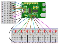
This tutorial will monitor 8 buttons and show their status with 8 LEDs. When a button is pressed, the corresponding LED will be turned on for 1 second. You will need your Raspberry Pi, an IO Pi Plus, 8 buttons, 8 LEDs and 8 300R resistors. The diagram to the right shows how the components will be connected, with the buttons on Bus 1 and the LEDs on Bus 2.
We will use the AB Electronics UK Python library to talk to the IO Pi. To download the library, visit our Python Library and Demos knowledge base article.
You must enable i2c on your Raspberry Pi; see our other tutorial on i2c: I2C, SMBus and Raspbian Linux.
The IO Pi Plus is supplied with Bus 1 on I2C address 0x20 and Bus 2 on 0x21; if you have changed the I2C addresses, you must update the code below to use the new I2C addresses.
The AB Electronics Python library uses another library called python3-smbus; you can install it using apt-get with the following commands.
sudo apt-get update
sudo apt-get install python3-smbus
With the libraries installed and the Raspberry Pi configured to use i2c, we can get started.
Stage 1 – Configuring the inputs and outputs
The first step will be configuring port 0 for the MCP23017 I/O controller on Bus 1 as inputs with the internal pull-up resistors enabled. The buttons connect the inputs to ground, so we will need to invert the inputs, making them appear as on or 1 when pressed and off or 0 when released.
We will start by creating a new Python program file called tutorial3.py. You can use your favourite text editor to write the program. You can find a complete example of tutorial3.py in the ABElectronics_Python_Libraries/ABElectronics_IOPi/demos folder.
At the top of your program, you will need to import the IOPI library and time library.
#!/usr/bin/env python
from IOPi import IOPi
import time
The IOPI library is used for all communication with your IO Pi. It gives you control over almost everything that can be done with the MCP23017 controller.
We will use both MCP23017 controllers, creating two instances of the IOPi class named busin and busout.
busin = IOPi(0x20)
busout = IOPi(0x21)
Next, we enable the internal pull-up resistors for port 0 on busin and set the port direction as inputs.
busin.set_port_pullups(0, 0xFF)
busin.set_port_direction(0, 0xFF)
As with Tutorial 2, we will invert port 0 so that a button press will register as a 1 instead of 0.
busin.invert_port(0, 0xFF)
Port 0 on busout will be configured as output pins to drive the LEDs. Set the port direction to 0x00 to configure all the pins as outputs, and write a value of 0x00 to the port to turn off all the LEDs.
busout.set_port_direction(0, 0x00)
busout.write_port(0, 0x00)
The inputs and outputs are working, so the next step is configuring the input pins' interrupts.
Stage 2 – Configuring the Interrupts
Interrupts can be triggered two ways: on stage change and when the pin does not match a default value.
The state change method will trigger the interrupt every time the input changes state from low to high or high to low. This is useful in many situations where you want to know that the input has changed, but when monitoring for a button press, the interrupt would trigger both when the button is pressed and when it is released. For this tutorial, we only want to update the LEDs when the button is pressed, so we will configure the interrupts to use the other option of triggering when the input does not match a default state.
The default state can be high or low and configured for each pin individually. We do this by setting each bit in an 8-bit number to 1 or 0 like you would when writing the output to a port. The interrupt will need to trigger when the button is pressed, and the input registers as going high or to 1, so we need to set the default value for the port as 0. We do this with the set_interrupt_defaults(port, value) method.
busin.set_interrupt_defaults(0, 0x00)
Next, we need to tell the interrupt logic that we want to use the default value instead of triggering on state change. This is done with the set_interrupt_type(port, value) method. For each pin:
0 = Trigger on state change
1 = Trigger when input does not match the default value
We want each pin on the port to trigger when the input does not match the default value so that we will set the port to 0xFF.
busin.set_interrupt_type(0, 0xFF)
Next, we want to turn the interrupt monitoring on for each pin on port 0. This is done with the set_interrupt_on_port(port, value) method.
busin.set_interrupt_on_port(0, 0xFF)
The final step before we can start monitoring the interrupts is to reset the interrupt status.
busin.reset_interrupts()
Stage 3 – Monitoring the interrupt status
The interrupts are now configured and monitoring the inputs. When a button is pressed, the input will go high, and the interrupt will trigger.
We must read the interrupt status regularly to check if an interrupt has been triggered. We can do this using a while loop.
while True:
The IOPi python library contains a method for checking the interrupt status read_interrupt_status(port). The method returns a value indicating the interrupt status for each pin on the selected port. When an interrupt is triggered, that pin's value will change from 0 to 1.
At this stage, we only want to know that a button has been pressed so we can read the interrupt status, and if the returned value is not 0, we know that an interrupt has occurred on one of the input pins.
We will use an if statement inside the while loop to check that the interrupt status is not 0.
if (busin.read_interrupt_status(0) != 0):
When an interrupt occurs, the value from the port is captured by the interrupt logic and can be read using the read_interrupt_capture(port) method.
Inside the if statement, copy the captured value into a variable called value.
value = busin.read_interrupt_capture(0)
The captured value will contain the button that was pressed. To light an LED for the same pin number on the busout bus, we can copy the value to the output port using the write_port(port, value) method.
busout.write_port(0, value)
Calling the read_interrupt_capture(port) or read_port(port) methods will reset the interrupts, preparing them for the following button press.
The last thing you need to add is time.sleep(200) outside the if statement to pause the program for 200ms on each loop.
time.sleep(0.2)
The sleep method will stop the program from using too much CPU time while giving a reasonable response time for any button presses.
Stage 4: Save and run the program
With the complete program, you can save and run the file with the following command.
python3 tutorial3.py
If everything works correctly, you should see an LED light each time you press a button. The LED should stay on until the next button is pressed.
(images created with Fritzing)
Table of Contents