The AB Electronics UK Knowledge Base provides support solutions, tutorials and troubleshooting guides.

In the IO Pi tutorial 3, we learned how to use an interrupt to monitor a button and turn on an LED when the button is pressed. In this tutorial, we will expand on Tutorial 3 by combining the IO Pi Plus interrupts with the GPIO interrupts on the Raspberry Pi.
By connecting the IO Pi Plus interrupts to the Raspberry Pi GPIO header, we can create an event-driven program that automatically calls a function when an interrupt occurs.
This is a more complicated way of monitoring pins on the IO Pi compared to the methods used in tutorials 2 and 3, but it does have the advantage that the inputs will be monitored in the background. By making the program event-driven, you can now do other things in your program without constantly checking the IO Pi to see if a button has been pressed or an interrupt occurred.
Getting Started
In this tutorial, we will monitor 8 buttons. When a button is pressed, the IO Pi Plus will send an interrupt event to the Raspberry Pi GPIO port, triggering the GPIO interrupt and printing a message on the display showing which button was pressed.
You will need your Raspberry Pi, an IO Pi Plus, 8 buttons, a 1K resistor and a 1.8K resistor. The diagram below shows how the components will be connected, with the buttons on Bus 1 and the IA pin on Bus 1 connected to GPIO 23 (pin 16) on the Raspberry Pi via a voltage divider.
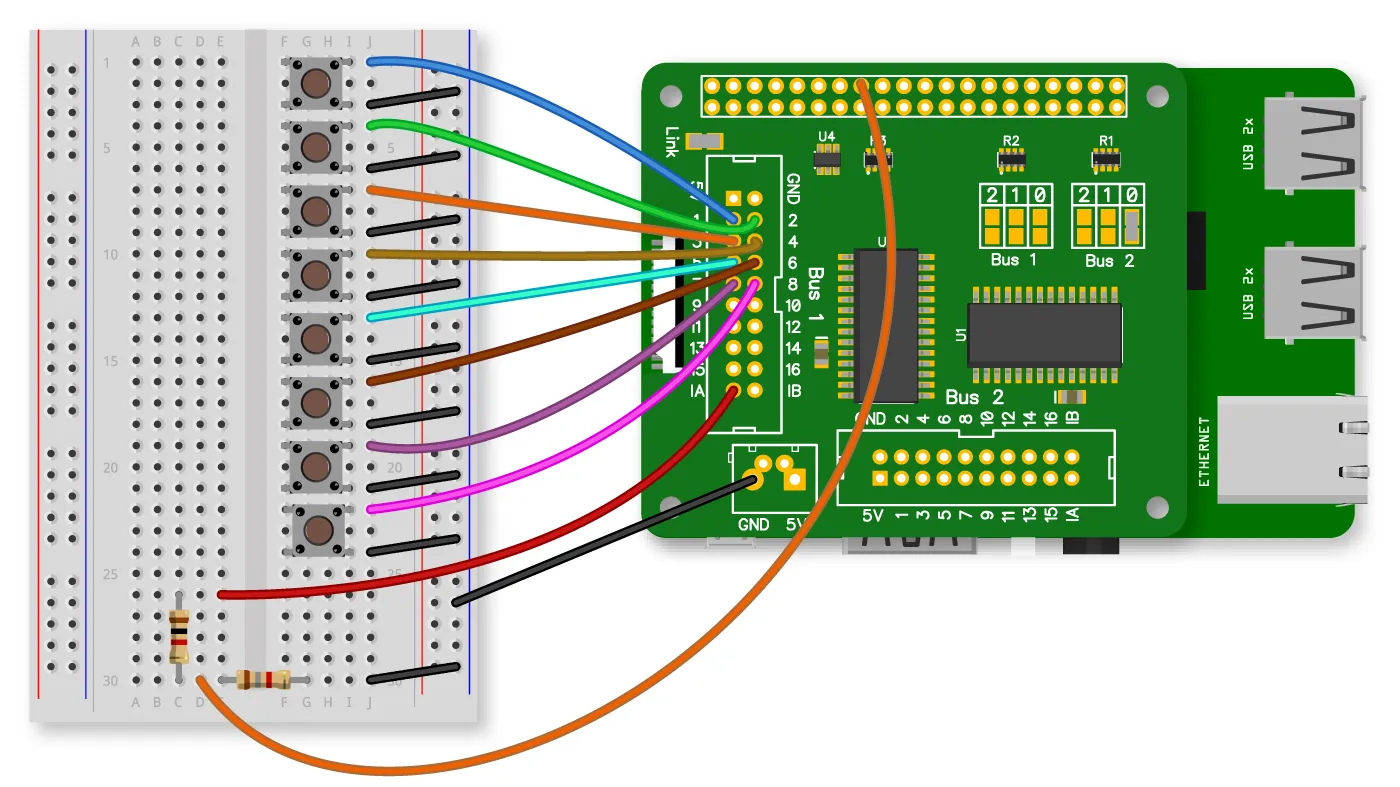
The IO Pi Plus operates at 5V, while the GPIO header on the Raspberry Pi operates at 3.3V. If you connected the IA pin on the IO Pi Plus directly to a GPIO pin, you would cause irreversible damage to the Raspberry Pi. For this reason, we need to convert the 5V down to 3.3V. A voltage divider with a 1K and 1.8K resistor can drop the voltage to a safe level. The diagram below shows how the resistors should be connected.

We will use the AB Electronics Python library to talk to the IO Pi Plus. To download the library, visit our Python Library and Demos knowledge base article.
You must enable I2C on your Raspberry Pi; see our other tutorial on I2C: I2C, SMBus and Raspbian Linux.
The IO Pi Plus is supplied with Bus 1 on I2C address 0x20 and Bus 2 on 0x21; if you have changed the I2C addresses, you must update the code below to use the new I2C addresses.
The AB Electronics Python library uses another library called python3-smbus; you can install it using apt-get with the following commands.
sudo apt-get update
sudo apt-get install python3-smbus
The RPi.GPIO library is needed to configure and listen for events on the Raspberry Pi’s GPIO header.
If you are using the Raspbian Linux distro, then RPi.GPIO should already be installed on your Raspberry Pi. If RPi.GPIO is not installed; you can install it using the following command.
sudo apt-get install python3-rpi.gpio
With the libraries installed and the Raspberry Pi configured to use i2c, we can get started.
We will start by creating a new Python program file called tutorial4.py. You can use your favourite text editor to write the program. You can find a complete example of tutorial4.py in the ABElectronics_Python_Libraries/ABElectronics_IOPi/demos folder.
At the top of your program, you must import the IOPI library, time library and RPi.GPIO library.
#!/usr/bin/env python
from IOPi import IOPi
import time
import RPi.GPIO as GPIO
Create a variable called bus with a value of None. The bus variable will be used later to control the IO Pi Plus, but we need to create a global variable that can be accessed by the main and sub-functions.
bus = None
In Python, functions must be declared before the main program, so next, we will declare the function, which is called when an interrupt event is triggered on the GPIO pin.
The GPIO event listener returns the number of the GPIO pin that called the event, so we will give the function a parameter called interrupt_pin. We will not be using it for this tutorial, but if you expand the program to work with more than one interrupt pin, this will be useful for finding out which pin called the function.
def button_pressed(interrupt_pin):
The global variable bus will be used, so we must declare it inside the scope of this function.
global bus
The button_pressed() function will read the capture value from the interrupts on port 0, find out which pin was triggered and print out a message to the display. First, we need to get the interrupt capture value and copy it into a variable called intval.
intval = bus.read_interrupt_capture(0)
This function will be called as soon as the button is pressed. To ensure the button_pressed() function is not called repeatedly while the button is depressed, we will need a while loop that reads the value from port 0 and compares it to the interrupt capture variable intval.
The while loop will continue looping until intval no longer matches port 0, which means the button has been released. A time.sleep() function call is added to create a 200ms delay between each loop to reduce the CPU load.
    while (intval ==  bus.read_port(0)):
        time.sleep(0.2)
Once the button has been released, we can find out which input on the port triggered the interrupt. We do this by looping through each bit in the intval variable and using a Boolean expression to check if it has a value of 1. If it equals 1, the button was pressed, and we can print a message to the display with that pin number.
    for num in range(0, 8):
        if (intval & (1 <<  num)):
            print("Pin " +  str(num + 1) + " pressed")
That is the end of the button_pressed(); now, we can continue with the main part of the program.
Define a new function called main.
def main():
As with the function above, the global variable bus will be used, so we must declare it inside the scope of this function.
global bus
Next, we define bus as an instance of the IOPi library with an I2C address of 0x20.
bus = IOPi(0x20)
Set port 0 as inputs with pull-up resistors enabled and the port inverted to make the input register as 1 when a button is connected to ground.
    bus.set_port_pullups(0,  0xFF)
    bus.set_port_direction(0, 0xFF)
    bus.invert_port(0, 0xFF)
With port 0 configured, the next step is to initialise and configure the interrupt logic.
We want the interrupt pin IA to be active low, pulling down the GPIO pin when the interrupt triggers; we can do this using the set_interrupt_polarity(polarity) method. set_interrupt_polarity(polarity) takes a parameter of 0 or 1 where 0 = active low and 1 = active high.
bus.set_interrupt_polarity(0)
The IA and IB interrupt pins can be configured as independent or mirrored. When configured as independent, an interrupt on port 0 will cause pin IA to change state, and port 1 will cause IB to change state. When mirrored, an interrupt event on port 0 or port 1 will cause both IA and IB to change state.
In this program, we want port 0 only to be mapped to the interrupt pin IA, so we will set the mirror option as 0 using the mirror_interrupts(value) method.
bus.mirror_interrupts(0)
Next, we will set the interrupt default value to 0x00 and the interrupt type to 0xFF so the interrupt triggers when any pin on port 0 goes from low to high or 0 to 1.
    bus.set_interrupt_defaults(0,  0x00)
    bus.set_interrupt_type(0, 0xFF)
Enable the interrupts for all pins on port 0 and call the reset_interrupts() method to reset the interrupt status.
    bus.set_interrupt_on_port(0, 0xFF)
    bus.reset_interrupts()
That is everything we need to do to set up and use the interrupts on the IO Pi Plus; now, we need to configure the interrupt on the Raspberry Pi GPIO 23 pin to trigger when the IO Pi interrupt pin goes low. We will be using the RPi.GPIO library to control the Raspberry Pi GPIO pin.
In the RPi.GPIO library, you can use the pin numbers (BOARD) or the Broadcom GPIO numbering mode (BCM). We will use BCM, so use the setmode() method to change the numbering mode to BCM.
GPIO.setmode(GPIO.BCM)
Next, we want to set GPIO 23 as an input and disable the internal pull-up resistor as the IO Pi Plus, and the voltage divider will pull the voltage high and low.
GPIO.setup(23, GPIO.IN, pull_up_down=GPIO.PUD_OFF)
To enable the interrupt on the GPIO pin, we will use the add_event_detect() method. add_event_detect() takes three parameters: the pin number, interrupt type, which can be rising, falling or both and the callback function, which will be called when an interrupt occurs. For this program, we want the interrupt to only trigger on a falling edge.
GPIO.add_event_detect(23, GPIO.FALLING, callback=button_pressed)
GPIO 23 pin is now configured for interrupts.
As this program doesn’t have a while loop constantly checking the IO Pi, we will need to add another way of keeping the program from ending when it reaches the end of the main function. We can do this using the input() function, which waits for input from the user’s keyboard.
input("press enter to exit ")
The last thing we need to add is a call to the main() function that will allow the program to run.
if __name__ ==  "__main__":
    main()
Save your program as tutorial4.py and run it with the following command.
python3 tutorial4.py
If everything works correctly, you should see a message on the screen saying, “press enter to exit”. When you press a button connected to pin 1, a message will appear “Pin 1 pressed”
To exit the program, press the enter key on your keyboard.
(images created with Fritzing)
Table of Contents