The AB Electronics UK Knowledge Base provides support solutions, tutorials and troubleshooting guides.

This tutorial is the first in a four-part series on the communication protocol I²C, explaining what it is, how it works and how you can use it on your Raspberry Pi.
For the other tutorials in this series, click on the links below.
- Part 1: Introducing I²C
- Part 2: Enabling I²C on the Raspberry Pi
- Part 3: I²C tools in Linux
- Part 4: Programming I²C with Python
What is I²C?
I²C, pronounced I-squared-C or I-2-C, is a popular serial communication protocol developed initially by Phillips Semiconductor, now known as NXP Semiconductor. Today I²C is used by most major IC manufacturers on a wide range of devices, from microcontrollers, ADCs and DACs to EEPROMs, I/O devices and real-time clocks.
I²C is designed to be a multi-slave, half-duplex bus meaning a master device can communicate with multiple slave devices connected to the same bus. Still, communication can only occur in one direction at a time. While I²C is designed to allow multiple master devices, on the Raspberry Pi, the Pi acts as the master, and all devices connected to the bus are slaves.
The I²C interface

The I²C bus uses two wires called SDA and SCL. The SDA (serial data) wire carries the data packets sent by the master and slave devices. The SCL (serial clock) wire carries a clock signal generated by the master and synchronises the data packets on the SDA wire between the master and slaves.
SDA and SCL are connected to the +Vdd power wire via pull-up resistors. This means the default state of the I²C bus is pulled high to the +Vdd voltage. Typical +Vdd voltages are 3.3V and 5V, although other voltages may be used.
Data is sent over the I²C bus by pulling the SDA wire low to 0V. The master generates the clock signals; slave devices send a data packet in response to a request from the master.
As the I²C bus uses the +Vdd voltage of the master device, all slave devices also typically work at the same voltage. If a slave device needs to work at a different voltage from the master, then an I²C level shifter can act as an interface between the various bus voltages.
I²C Addresses
Each slave device on the I²C bus must have a unique address. The I²C protocol allows a 7-bit or 10-bit address system, although 10-bit addressing is rarely used. 7-bit addressing gives an allowable address range of 0x03 to 0x77. The master device will send the address at the start of any communication, and only the slave device on that address will respond.
Suppose a circuit requires several slave devices that share the same I²C address. An I²C switch may be used, which splits an I²C bus into several separate buses, with each slave connected to its own sub-bus. Before communicating with one of the slaves, the switch can be set to channel with the required slave, and only that slave will be visible to the master.
Some I²C devices include an All-Call address, which can send data to several slave devices simultaneously. While those devices will receive data on the All-Call address, each device will only send data back to the master at its unique address.
I²C Protocol

The graphic above shows a typical I²C data packet with a 7-bit address.
Each byte in an I²C packet is 8 bits long, followed by a 9th acknowledge bit generated by the receiving slave device pulling the SDA wire low for one clock cycle. An acknowledge bit is typically shown in I2C software as ACK. If a slave does not acknowledge the byte, the acknowledge bit is shown as a NACK.
The start and end of the data packet are the start and stop conditions. The master always generates the start and stop conditions.
- Start: High to Low transition on SDA while SCL is high.
- Stop: Low to High transition on SDA while SCL is high.
After the start condition, an address byte is sent by the master.
7-bit addresses
The address byte consists of 7 address bits followed by a Read/Write bit. The Read/Write bit is set as 1 when reading data from the slave and 0 when writing data to a slave.
10-bit addresses

In a 10-bit address packet, the address is contained within the first two bytes. The first address byte consists of four 1s, one 0, two address bits, and the Read/Write bit. The second address byte consists of the eight remaining bits.
After the master has sent the address, the data bytes will be sent or received. The master generates the clock cycles on the SCL wire, so in a read condition, the slave will wait for each cycle before sending its data by pulling the SDA wire high or low.
Clock Speeds
I²C initially supported a clock speed of 100 Kbit/s. Over time, the clock speed was increased to support new devices, and today, compliant hardware supports the following clock speeds:
- 100 Kbit/s – Standard Mode
- 400 Kbit/s – Full Speed
- 1 Mbit/s – Fast Mode
- 3.2 Mbit/s – High Speed
Not all devices support speeds above 100 Kbit/s, so check the device's datasheet to find the supported clock speeds.
Clock Stretching
If a slave device requires more time to perform another function before sending a response, it can pull the SCL wire low, forcing the master to wait until it is ready. This action is known as clock stretching.
You can find more information on how I²C works in the I²C Manual from Phillips/NXP.
Note: documents in Portable Document Format (PDF) require Adobe Acrobat Reader 5.0 or higher to view, download Adobe Acrobat Reader or other PDF reading software for your computer or mobile device.
Also useful for your Raspberry Pi project
Temperature & Sensing
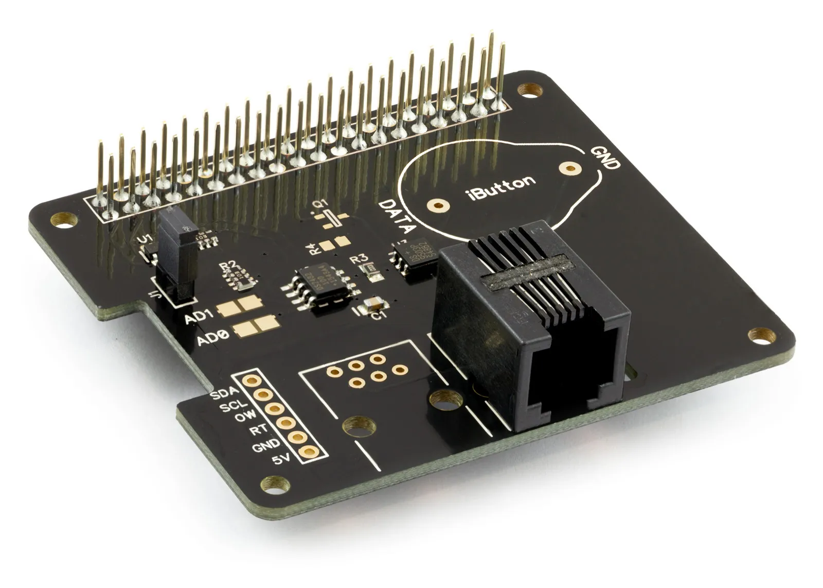
1 Wire Pi Plus
Connect dozens of 1-Wire sensors - temperature, iButtons, EEPROMs - via a single GPIO pin. Stacks directly on the 40-pin header.
Analogue I/O
ADC Pi
Read up to 8 analogue inputs - perfect for pairing with your temperature sensors or other analogue-output devices.
All-in-one
Expander Pi
Combines ADC, DAC, 32 GPIO ports and a real-time clock on one board. The most versatile board for complex Raspberry Pi projects.
Chapters
Related Articles
- Raspberry Pi GPIO Pins
- PCB Header Assembly Jig
- Samba Setup on Raspberry Pi
- Set a static IP Address on Raspberry Pi OS Trixie
- Set a static IP Address on Raspberry Pi OS Buster
- Set a static IP Address on Raspberry Pi OS Wheezy
- I2C Part 1 - Introducing I2C
- I2C Part 2 - How to Enable I2C on the Raspberry Pi
- I2C Part 3 - I2C tools in Linux
- I2C Part 4 - Programming I2C with Python
- SPI and Python on Raspberry Pi OS
- Using Pythonpath with our Python Libraries
- Connecting Development Boards to the Raspberry Pi 400
Order these Boards
1 Wire Pi Plus
1 Wire interface development board for the Raspberry Pi and Single-Board Computers
£11.99 ex VAT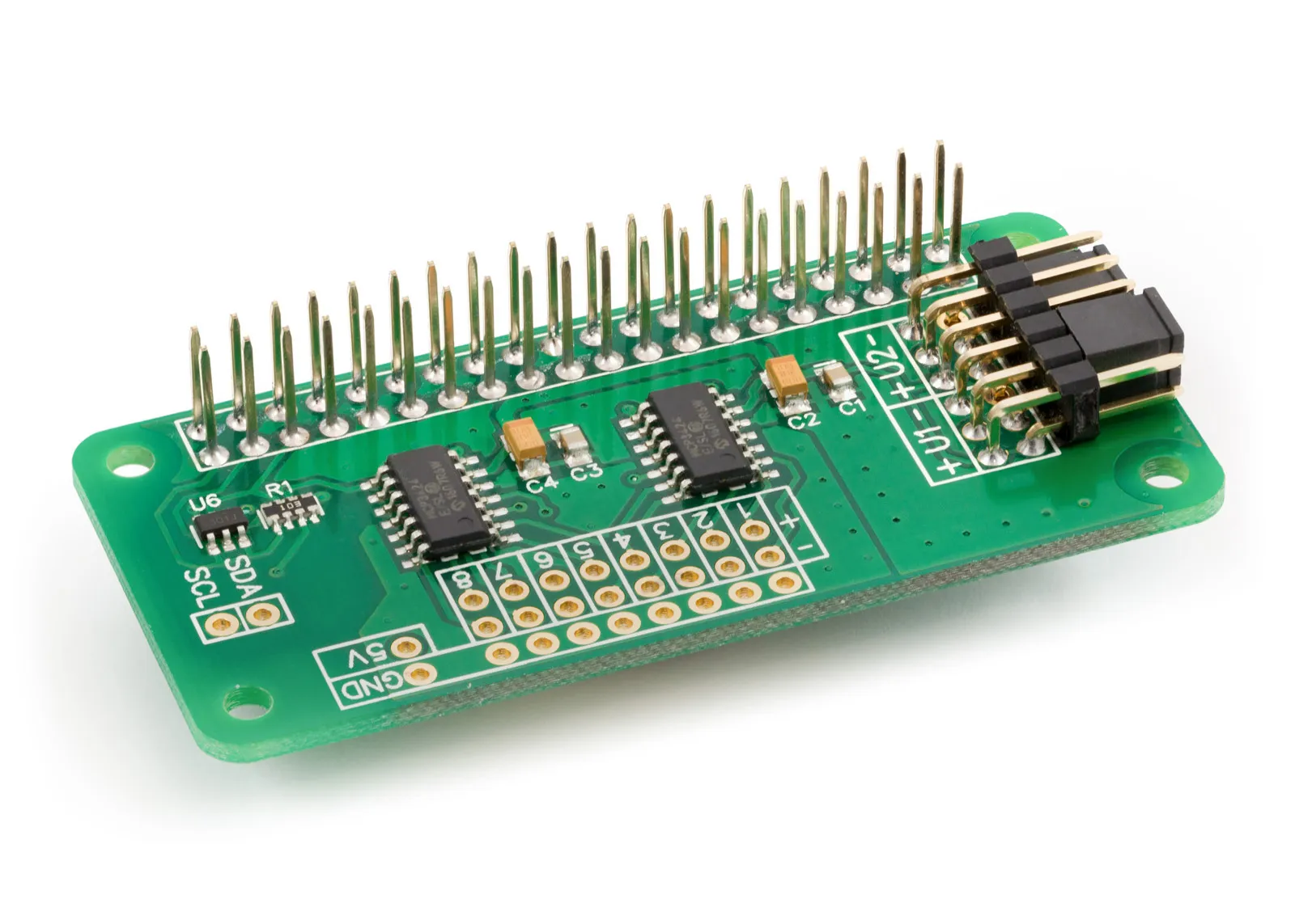
ADC Differential Pi
8 Channel 18-bit Differential Analogue to Digital converter development board for the Raspberry Pi
£16.99 ex VAT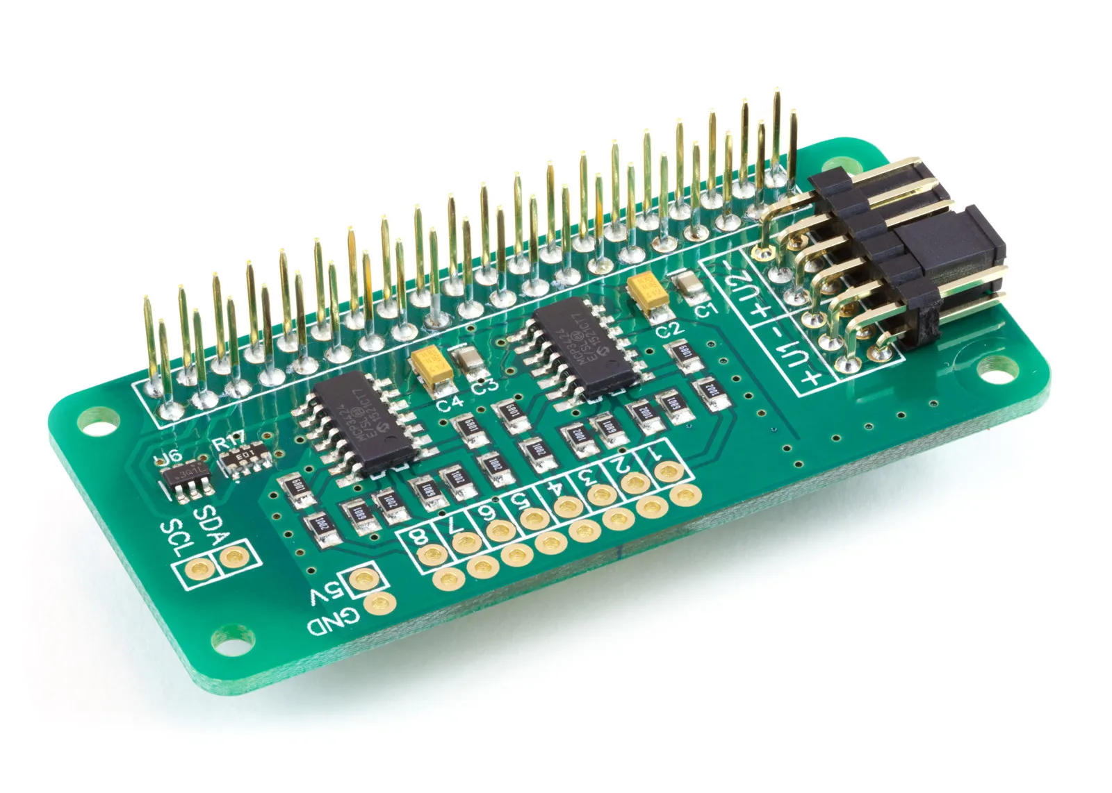
ADC Pi
8 Channel 17-bit Single-Ended Analogue to Digital Converter for the Raspberry Pi and Single-Board Computers
£17.99 ex VAT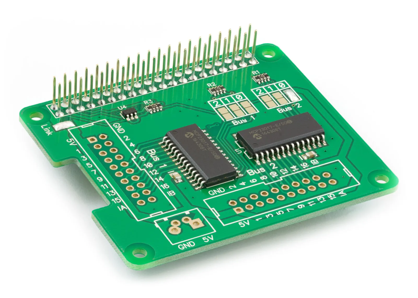
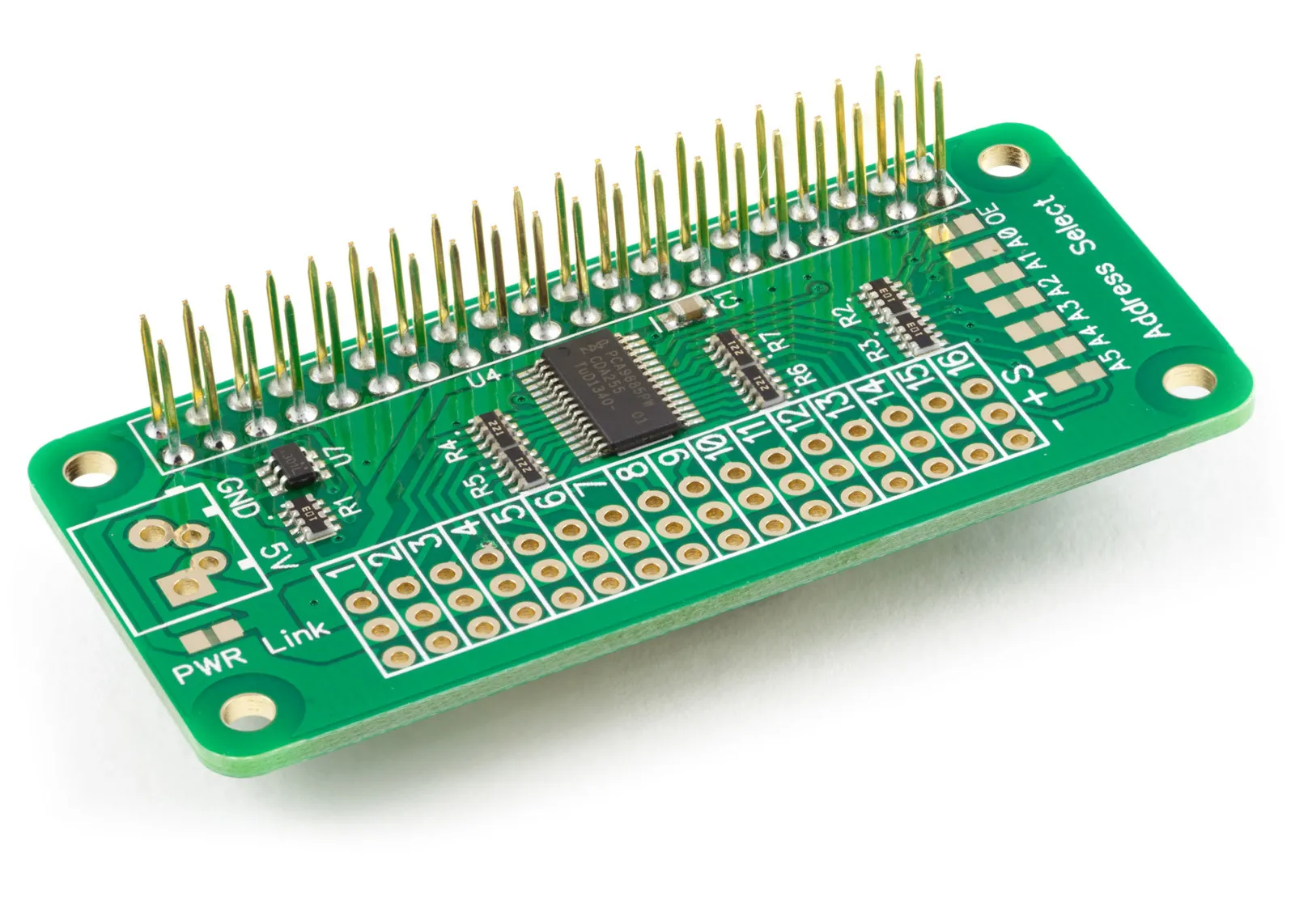
Servo PWM Pi
16 Channel 12-bit PWM and Servo Driver with I2C interface using PCA9685 for driving LEDs and RC servos
£9.49 ex VAT
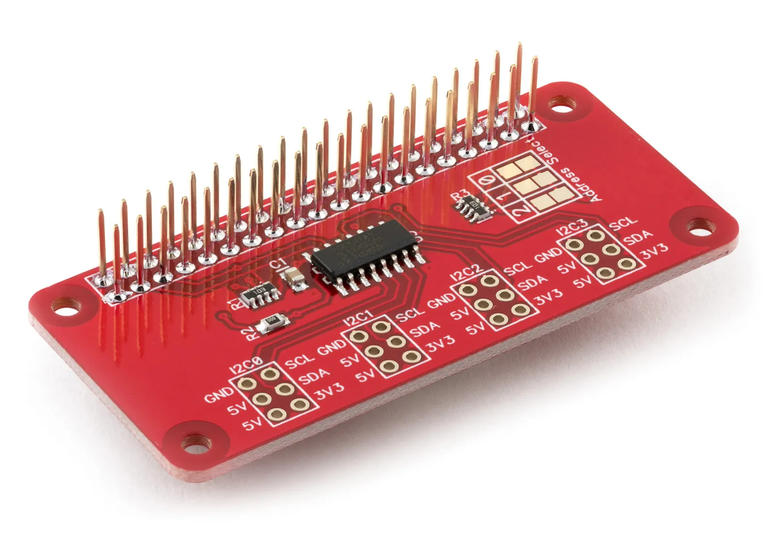
I2C Switch
4 Channel PCA9546 I2C Multiplexer for the Raspberry Pi and Single-Board Computers
£6.99 ex VAT