The AB Electronics UK Knowledge Base provides support solutions, tutorials and troubleshooting guides.

This tutorial is the fourth in a four-part series on the communication protocol I²C, explaining what it is, how it works and how you can use it on your Raspberry Pi.
For the other tutorials in this series, click on the links below.
- Part 1: Introducing I²C
- Part 2: Enabling I²C on the Raspberry Pi
- Part 3: I²C tools in Linux
- Part 4: Programming I²C with Python
Python is one of Raspberry Pi's most popular programming languages and is used for many applications, from controlling hardware to web development. This tutorial will examine how you use Python to control a device connected to the Raspberry Pi's I²C bus.
The device we will be controlling is an MCP23017 I/O controller from Microchip. It is a popular I/O interface with 16 GPIO pins and is used on our IO Pi Plus and Expander Pi development boards. While this tutorial targets the MCP23017, the same principles apply to almost all I²C devices.
The code for this tutorial can be found on our GitHub repository.
The MCP23017 – A Quick Overview
View the datasheet for the MCP23017.
The MCP23017 has 16 bidirectional I/O pins split into two 8-bit ports named Port A and Port B. Port A controls pins 1 to 8, while Port B controls pins 9 to 16.
Control of these I/O pins is done by reading and writing to registers within the chip. A register is a section of memory, in this case, 8 bits, accessed from a specified address. In the MCP23017, there are 21 registers: 10 associated with Port A, 10 with Port B, and a control register shared between both ports. We will go into more detail on how some of the registers work later in the tutorial, but you can find a list of the registers and their functions on page 17 in the datasheet.
Using Hexadecimal
When working with hardware like I²C buses, you will generally see numbers in programs and device datasheets in hexadecimal format. Computers typically deal with numbers as bytes. A byte is a value of 8 bits in size.
There are several ways of representing an 8-bit number. You could use binary to show each of the 8 bits individually 10000111. In decimal, the same number would be shown as 135. In hexadecimal, the number would be displayed as 87.
Hexadecimal has the advantage that any 8-bit number can be represented with two characters, so 11111111 becomes 255 in decimal and FF in hexadecimal. This makes it easy to see how many bytes a number contains based on the number of characters. The number of bytes is always the number of characters divided by two.
- 00 = 1 byte or 8 bits
- 0000 = 2 bytes or 16 bits
- 00000000 = 4 bytes or 32 bits.
In Python, to represent a hexadecimal number, the character "0x" is added to the beginning of the number, for example, "0xFE". Binary numbers have "0b" added to the front of the number, for example, "0b11111110".
In this tutorial, all the numbers will be shown in hexadecimal format. To help you convert numbers between binary, decimal and hexadecimal, we have a converter on our website at Electronics Toolbox Value Converter.
Getting Started
Before we can start writing code to talk to the I²C bus, we will need a basic template for a Python program. The code below is everything you need to begin.
#!/usr/bin/env python

def main():
    '''
    Main program function
    '''


if __name__ == "__main__":
    main()
The smbus Library
To connect to the I²C bus in Python, you will need a library that talks to the Raspberry Pi hardware. We will use the smbus library for this tutorial, which is included with the Raspberry Pi OS Linux distribution.
At the top of your program, below the first line, import the SMBus class from the smbus library.
from smbus import SMBus
The time.sleep function is used to pause the program, so you will need to import the time library as well.
import time
The SMBus class includes a range of functions to read and write to the I²C bus. A summary of the available functions is listed below.
|
Function |
Description |
Parameters |
Return value |
|---|---|---|---|
|
write_quick(addr) |
Quick transaction. |
int addr |
long |
|
read_byte(addr) |
Read Byte transaction. |
int addr |
long |
|
write_byte(addr,val) |
Write Byte transaction. |
int addr, char val |
long |
|
read_byte_data(addr,cmd) |
Read Byte Data transaction. |
int addr, char cmd |
long |
|
write_byte_data(addr,cmd,val) |
Write Byte Data transaction. |
int addr, char cmd, char val |
long |
|
read_word_data(addr,cmd) |
Read Word Data transaction. |
int addr, char cmd |
long |
|
write_word_data(addr,cmd,val) |
Write Word Data transaction. |
int addr, char cmd, int val |
long |
|
process_call(addr,cmd,val) |
Process Call transaction. |
int addr, char cmd, int val |
long |
|
read_block_data(addr,cmd) |
Read Block Data transaction. |
int addr, char cmd |
long[] |
|
write_block_data(addr,cmd,vals) |
Write Block Data transaction. |
int addr, char cmd, long[] |
None |
|
block_process_call(addr,cmd,vals) |
Block Process Call transaction. |
int addr, char cmd, long[] |
long[] |
|
Function |
Description |
Parameters |
Return value |
|---|---|---|---|
|
read_i2c_block_data(addr,cmd) |
Block Read transaction. |
int addr, char cmd |
long[] |
|
write_i2c_block_data(addr,cmd,vals) |
Block Write transaction. |
int addr, char cmd, long[] |
None |
The functions we will be using for this tutorial are write_byte_data(), write_word_data() and read_byte_data(), which allow you to write and read data from register addresses on an I²C device.
Defining the Registers
The MCP23017 has 21 registers used to control the device, numbered 0x00 to 0x15. For example, to set the direction of Port B, you would write to register 0x01 and to read from Port A, you read the register 0x12. The program could be written by reading and writing to registers using their numbered address; however, this would make the code hard to read, especially when you come back after several months and cannot remember what each number means. To simplify, we will give each register a name based on its function. The datasheet for the MCP23017 includes a list of names for the registers, so we will use those.
Most programming languages can create a read-only variable called a constant. Python cannot define a constant variable, so the convention is to show it as read-only using all capital letters. As the register addresses will not change, we will use capitalised names for each variable.
Inside the main() function, add the list of register addresses.
    # Define registers values from datasheet
    IODIRA = 0x00  # IO direction A - 1= input 0 = output
    IODIRB = 0x01  # IO direction B - 1= input 0 = output
    IPOLA = 0x02  # Input polarity A
    IPOLB = 0x03  # Input polarity B
    GPINTENA = 0x04  # Interrupt-onchange A
    GPINTENB = 0x05  # Interrupt-onchange B
    DEFVALA = 0x06  # Default value for port A
    DEFVALB = 0x07  # Default value for port B
    INTCONA = 0x08  # Interrupt control register for port A
    INTCONB = 0x09  # Interrupt control register for port B
    IOCON = 0x0A  # Configuration register
    GPPUA = 0x0C  # Pull-up resistors for port A
    GPPUB = 0x0D  # Pull-up resistors for port B
    INTFA = 0x0E  # Interrupt condition for port A
    INTFB = 0x0F  # Interrupt condition for port B
    INTCAPA = 0x10  # Interrupt capture for port A
    INTCAPB = 0x11  # Interrupt capture for port B
    GPIOA = 0x12  # Data port A
    GPIOB = 0x13  # Data port B
    OLATA = 0x14  # Output latches A
    OLATB = 0x15  # Output latches B
Creating an SMBus Object
The SMBus object represents the physical I²C bus on the Raspberry Pi. All commands to send and receive data go through the SMBus object, so for our program to access the I²C bus, we will have to create an instance of the SMBus object.
SMBus takes a single parameter: the ID of the I²C bus you want to use. The original Raspberry Pi models A and B with a 26-pin GPIO header had a bus ID of 0, while newer models with a 40-pin GPIO header have a bus ID of 1.
Create an instance of the SMBus object called i2cbus under the list of register addresses.
i2cbus = SMBus(1) # Create a new I2C bus
Device Address
Each device on the I²C bus has a unique 7-bit address. More details on how I²C addresses work can be found in the first part of our I²C tutorial series.
The MCP23017 has three address pins, which allow the user to set an I²C address from 7 possible options between 0x20 and 0x27 by setting each address pin high or low. The default address when all address pins are low is 0x20, so we will use this address for this tutorial. If your device is set to a different address, you can use that value.
Create a variable called i2caddress with a value of 0x20.
i2caddress = 0x20 # Address of MCP23017 device
The Control Register
If you have read through the datasheet for the MCP23017, you may have noticed that the chip has two lists of register addresses. In the first list, the registers associated with each port are separated into different banks, while in the second list, the registers are in the same bank, and the addresses are sequential. To ensure our list of register variables points to the correct addresses, we must tell the MCP23017 which version of the register list we want to use. We do this by setting the control register.
The control register IOCON is 8 bits, and each bit controls a different part of the chip's functions. A list of the bits and their use is shown below.
|
Bit |
Function |
|---|---|
|
7 |
BANK: Controls how the registers are addressed |
|
6 |
MIRROR: INT Pins Mirror bit 1 = The INT pins are internally connected 0 = The INT pins are not connected. INTA is associated with PORTA, and INTB is associated with PORTB |
|
5 |
SEQOP: Sequential Operation mode bit 1 = Sequential operation disabled; address pointer does not increment. 0 = Sequential operation enabled; address pointer increments |
|
4 |
DISSLW: Slew Rate control bit for SDA output 1 = Slew rate disabled 0 = Slew rate enable |
|
3 |
HAEN: Hardware Address Enable bit (MCP23S17 only) 1 = Enables the MCP23S17 address pins. 0 = Disables the MCP23S17 address pins |
|
2 |
ODR: Configures the INT pin as an open-drain output 1 = Open-drain output (overrides the INTPOL bit.) 0 = Active driver output (INTPOL bit sets the polarity. |
|
1 |
INTPOL: This bit sets the polarity of the INT output pin 1 = Active-high 0 = Active-low |
|
0 |
Unimplemented: Read as '0' |
The register banks are controlled using bit 7, and we want the register addresses to be sequential, so we will set that bit to 0.
Using sequential register addresses allows us to update both ports on the bus simultaneously by writing to two register addresses sequentially with two bytes. To enable this, we must enable sequential operation mode by setting bit 5 to 0.
By default, the two interrupt pins are set as active low; this means that the two pins will be outputting power when the interrupt functionality is not being used. We can set the pins to be off by default by setting bit 1 to 1.
Bits 6, 4, 3, 2 and 0 can be left in their default state of 0, so the only bit that needs to be set to 1 is bit 1. This gives us a value of 0b00000010 or 0x02.
To write the value to the IOCON register, we will use the write_byte_data(address, register, value) function. write_byte_data takes three parameters: the device address, the register to write to, and the 8-bit value to be written. We want to write to the I²C address defined in the i2caddress variable, the IOCON register and a value of 0x02, so we will add the following code to the program.
i2cbus.write_byte_data(i2caddress, IOCON, 0x02) # Update configuration register
Setting the Port Direction
Each pin on the MCP23017 can be individually set as an input or output. Two registers, IODIRA and IODIRB, control the direction of the ports. IODIRA controls Port A, pins 1 to 8, and IODIRB controls Port B, pins 9 to 16. To set a pin as an input, a value of 1 is used; to set it as an output, a value of 0 is used.
This tutorial will set Port A as outputs and Port B as inputs. We could do this by using the write_byte_data() function twice, first to update IODIRA and then IODIRB. Still, we enabled sequential writing in the control register, which means we can update both direction registers by writing two bytes to the device. We will use the write_word_data(address, register, value) function. write_word_data takes the same address and register values as the write_byte_data function but takes a 16-bit value for its third parameter.
By writing a 16-bit value to the I²C bus at the address of the IODIRA register, the MCP23017 will update the IODIRA register with the lower 8 bits and the IODIRB register with the upper 8 bits, allowing us to update all 16 pins in one operation.
To set pins 1 to 8 as outputs, we set their values to 0, and to set pins 9 to 16 as inputs, we set their values to 1. To update all of the pins at the same time, we will need to write 0b1111111100000000 or 0xFF00 to the IODIRA register. Add the following code to the program.
i2cbus.write_word_data(i2caddress, IODIRA, 0xFF00) # Set Port A as outputs and Port B as inputs
Reading and Writing to the Ports
With the configuration register set and port direction configured, we can begin reading from and writing to the ports.
First, create a while loop which will run forever.
while (True):
We will use the read_byte_data(address, register) function to read the inputs on Port B. read_byte_data takes two parameters, the device address and the target register, and returns a single byte.
We set Port B as inputs so we will read from the GPIOB register, store it in a variable called portb and print that variable to the console.
        portb = i2cbus.read_byte_data(i2caddress, GPIOB)  # Read the value of Port B
        print(portb) # print the value of Port B
To write a value to Port A, we have two options: write directly to the GPIOA register or the output latches using the OLATA register.
When you write to the GPIO register, the value is sent directly to the port, updating all the pins. Writing to the OLAT register only updates the pins, which are set as outputs. As we have set all the pins on Port A as outputs, there will be no difference between writing to the GPIO or OLAT registers, so we will update the pins by writing directly to the GPIO register.
To see a change in the output on a multimeter, oscilloscope or logic analyser, we will turn pin 1 on, sleep for 500 milliseconds, turn pin 1 off and wait for another 500 milliseconds. This will give us a square wave of approximately 1 second. It will not be precisely 1 second as we also read from Port B in each loop, which takes around 2 milliseconds to complete when the I²C clock frequency is 100KHz.
We will write to the GPIOA register using the write_byte_data() function with a value of 0x01 to turn on only pin 1 and write a value of 0x00 to turn pin 1 off. The time.sleep() function will wait 500ms between each write function call.
        i2cbus.write_byte_data(i2caddress, GPIOA, 0x01)  # Set pin 1 to on
        time.sleep(0.5)  # Wait 500ms

        i2cbus.write_byte_data(i2caddress, GPIOA, 0x00)  # Set pin 1 to off
        time.sleep(0.5)  # Wait 500ms
Running the Program
Your program should now be complete and ready to run. The full code is shown below.
#!/usr/bin/env python

from smbus import SMBus
import time

def main():
    '''
    Main program function
    '''
    # Define registers values from datasheet
    IODIRA = 0x00  # IO direction A - 1= input 0 = output
    IODIRB = 0x01  # IO direction B - 1= input 0 = output
    IPOLA = 0x02  # Input polarity A
    IPOLB = 0x03  # Input polarity B
    GPINTENA = 0x04  # Interrupt-onchange A
    GPINTENB = 0x05  # Interrupt-onchange B
    DEFVALA = 0x06  # Default value for port A
    DEFVALB = 0x07  # Default value for port B
    INTCONA = 0x08  # Interrupt control register for port A
    INTCONB = 0x09  # Interrupt control register for port B
    IOCON = 0x0A  # Configuration register
    GPPUA = 0x0C  # Pull-up resistors for port A
    GPPUB = 0x0D  # Pull-up resistors for port B
    INTFA = 0x0E  # Interrupt condition for port A
    INTFB = 0x0F  # Interrupt condition for port B
    INTCAPA = 0x10  # Interrupt capture for port A
    INTCAPB = 0x11  # Interrupt capture for port B
    GPIOA = 0x12  # Data port A
    GPIOB = 0x13  # Data port B
    OLATA = 0x14  # Output latches A
    OLATB = 0x15  # Output latches B

    i2cbus = SMBus(1)  # Create a new I2C bus
    i2caddress = 0x20  # Address of MCP23017 device

    i2cbus.write_byte_data(i2caddress, IOCON, 0x02)  # Update configuration register

    i2cbus.write_word_data(i2caddress, IODIRA, 0xFF00)  # Set Port A as outputs and Port B as inputs

    while (True):
        portb = i2cbus.read_byte_data(i2caddress, GPIOB)  # Read the value of Port B
        print(portb) # print the value of Port B

        i2cbus.write_byte_data(i2caddress, GPIOA, 0x01)  # Set pin 1 to on
        time.sleep(0.5)  # Wait 500ms

        i2cbus.write_byte_data(i2caddress, GPIOA, 0x00)  # Set pin 1 to off
        time.sleep(0.5)  # Wait 500ms


if __name__ == "__main__":
    main()
Save your Python program as i2c.py and run it using the following command.
python i2c.py
Pin 1 on Port A will output a square wave, and the value from Port B should be written to the console every second in decimal format. Pulling a pin high by connecting it to a voltage source will change the number displayed; for example, setting pin 12 high will be read as 8 or 0b00001000.
Conclusion
In this tutorial, we have learned how to use Python to create an I²C SMBus object and read from and write to registers in a device. While the code here was used on the MCP23017 chip, it can be modified to work with many I²C devices.
Note: documents in Portable Document Format (PDF) require Adobe Acrobat Reader 5.0 or higher to view, download Adobe Acrobat Reader or other PDF reading software for your computer or mobile device.
Also useful for your Raspberry Pi project
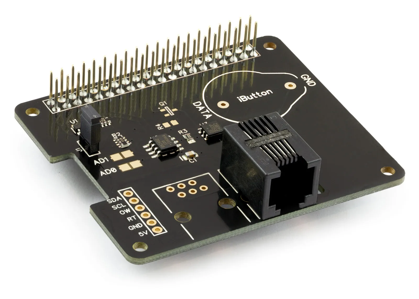
Temperature & Sensing
1 Wire Pi Plus
Connect dozens of 1-Wire sensors - temperature, iButtons, EEPROMs - via a single GPIO pin. Stacks directly on the 40-pin header.
Analogue I/O
ADC Pi
Read up to 8 analogue inputs - perfect for pairing with your temperature sensors or other analogue-output devices.
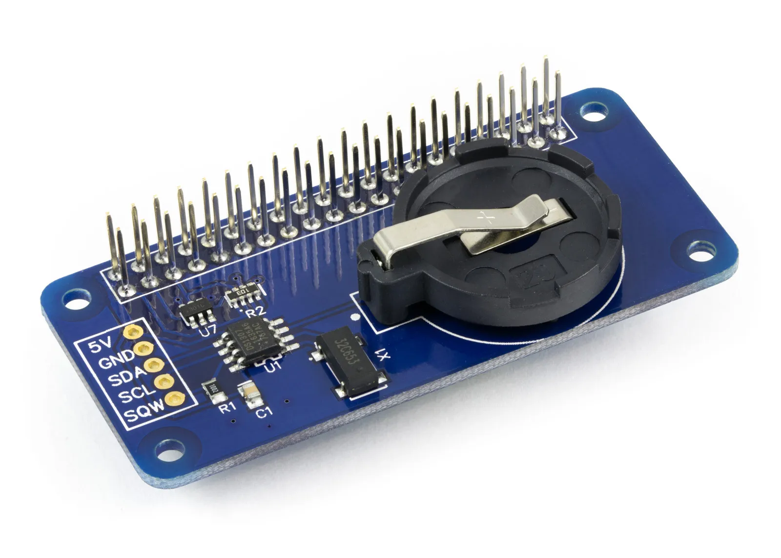
All-in-one
Expander Pi
Combines ADC, DAC, 32 GPIO ports and a real-time clock on one board. The most versatile board for complex Raspberry Pi projects.
Chapters
Related Articles
- Raspberry Pi GPIO Pins
- PCB Header Assembly Jig
- Samba Setup on Raspberry Pi
- Set a static IP Address on Raspberry Pi OS Trixie
- Set a static IP Address on Raspberry Pi OS Buster
- Set a static IP Address on Raspberry Pi OS Wheezy
- I2C Part 1 - Introducing I2C
- I2C Part 2 - How to Enable I2C on the Raspberry Pi
- I2C Part 3 - I2C tools in Linux
- I2C Part 4 - Programming I2C with Python
- SPI and Python on Raspberry Pi OS
- Using Pythonpath with our Python Libraries
- Connecting Development Boards to the Raspberry Pi 400
Order these Boards
1 Wire Pi Plus
1 Wire interface development board for the Raspberry Pi and Single-Board Computers
£11.99 ex VAT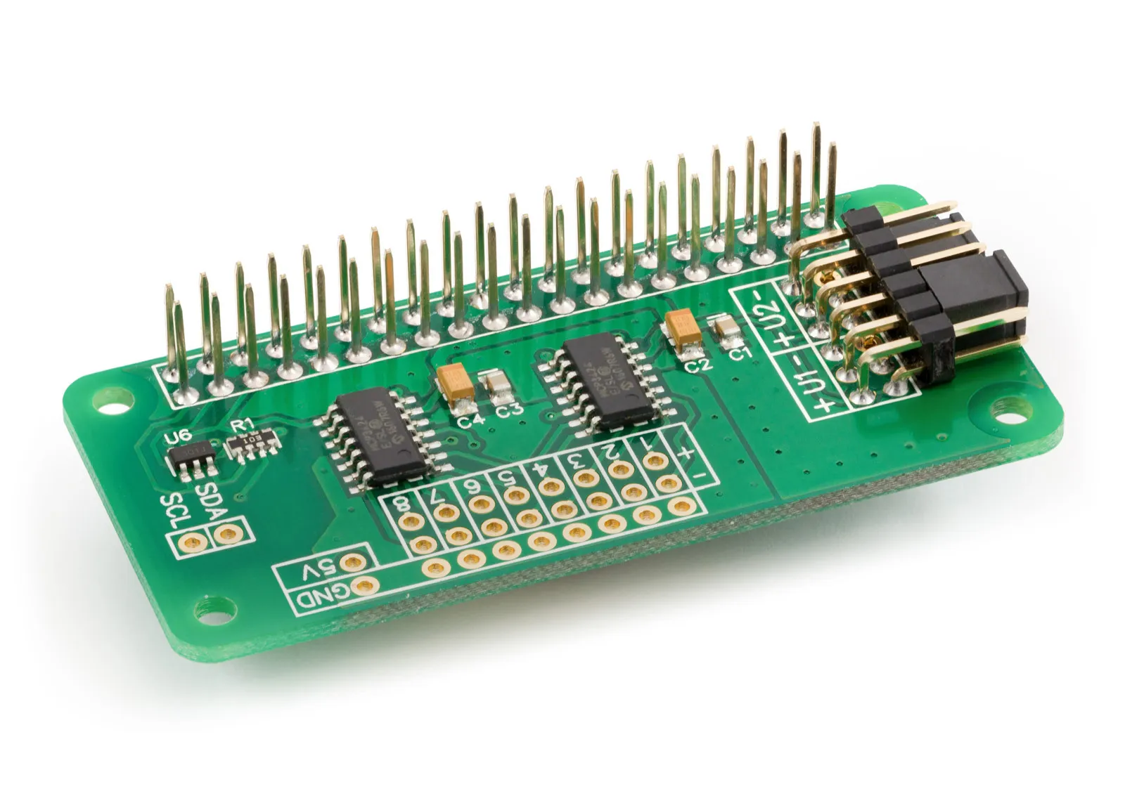
ADC Differential Pi
8 Channel 18-bit Differential Analogue to Digital converter development board for the Raspberry Pi
£16.99 ex VAT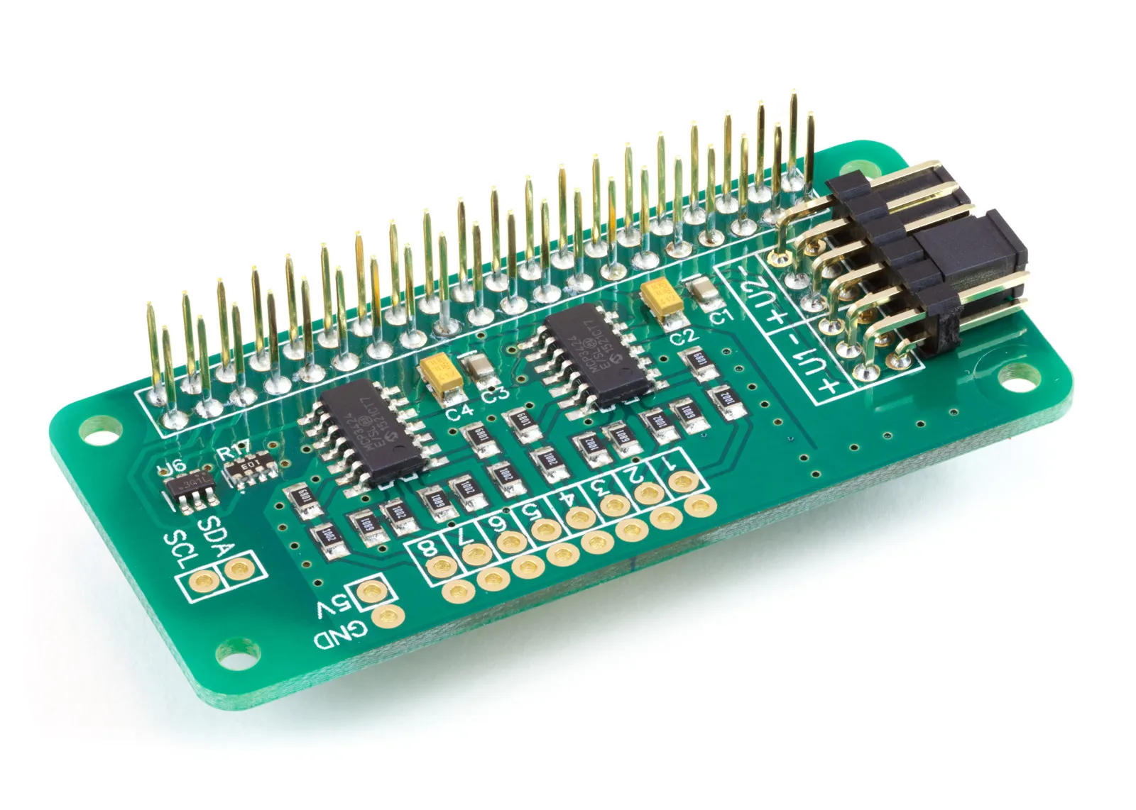
ADC Pi
8 Channel 17-bit Single-Ended Analogue to Digital Converter for the Raspberry Pi and Single-Board Computers
£17.99 ex VAT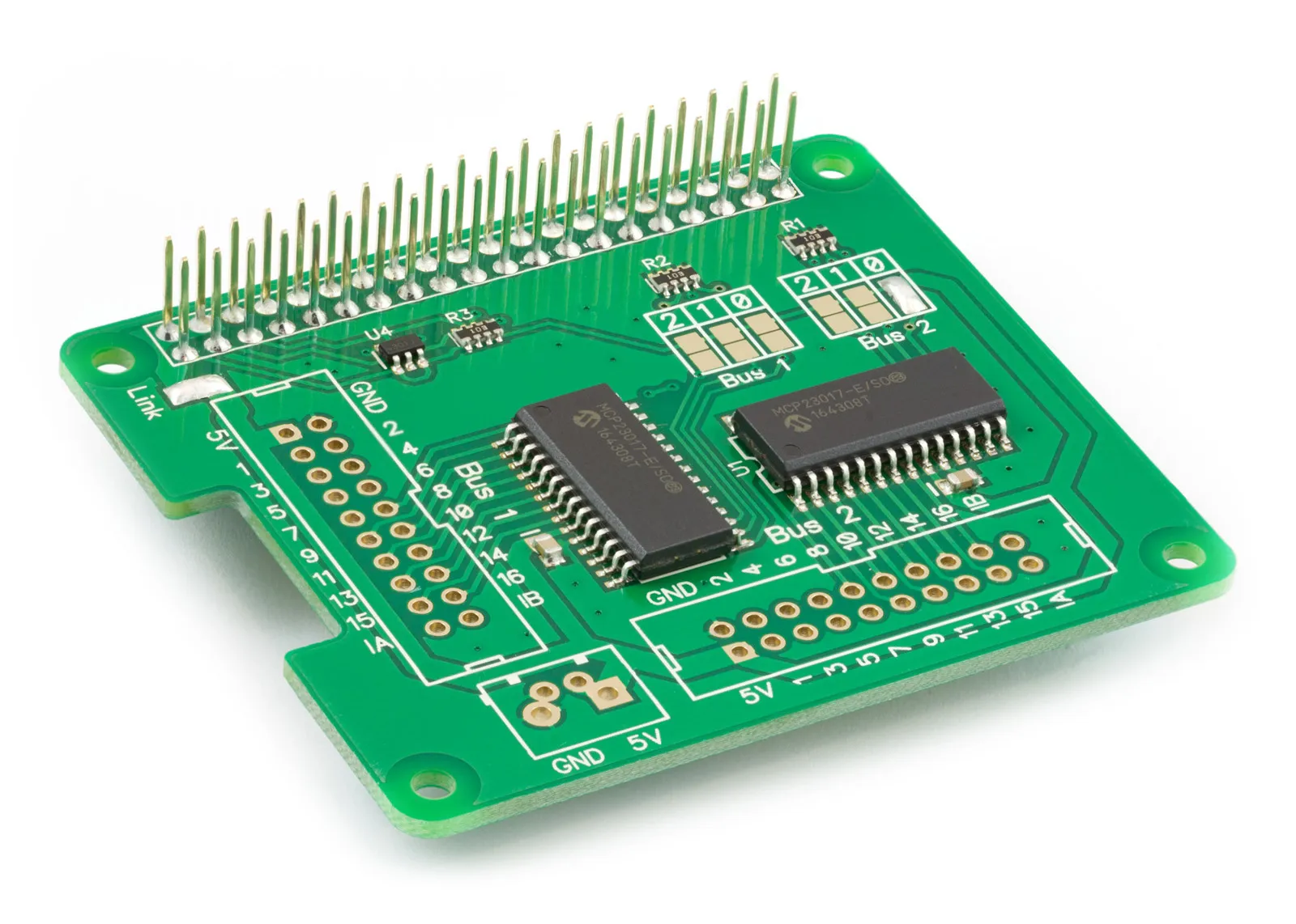
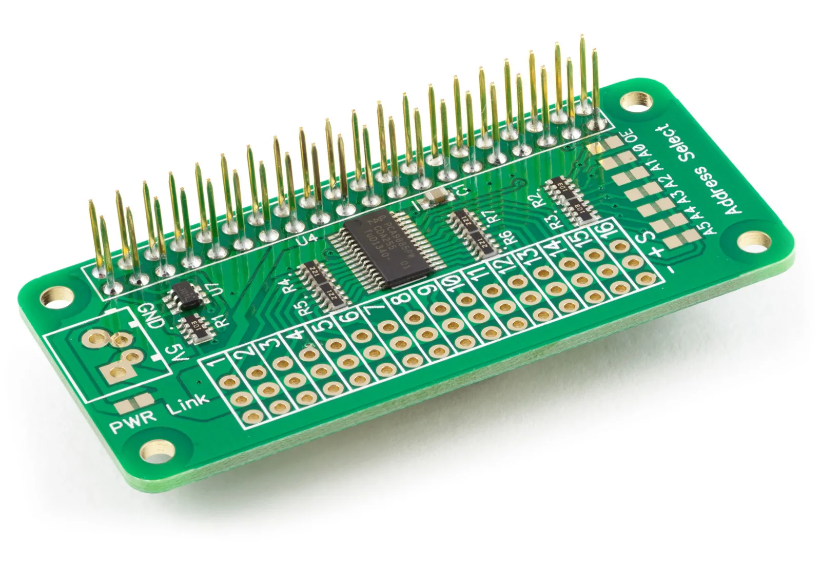
Servo PWM Pi
16 Channel 12-bit PWM and Servo Driver with I2C interface using PCA9685 for driving LEDs and RC servos
£9.49 ex VAT