The AB Electronics UK Knowledge Base provides support solutions, tutorials and troubleshooting guides.

YOU WILL NEED THIS BOARD
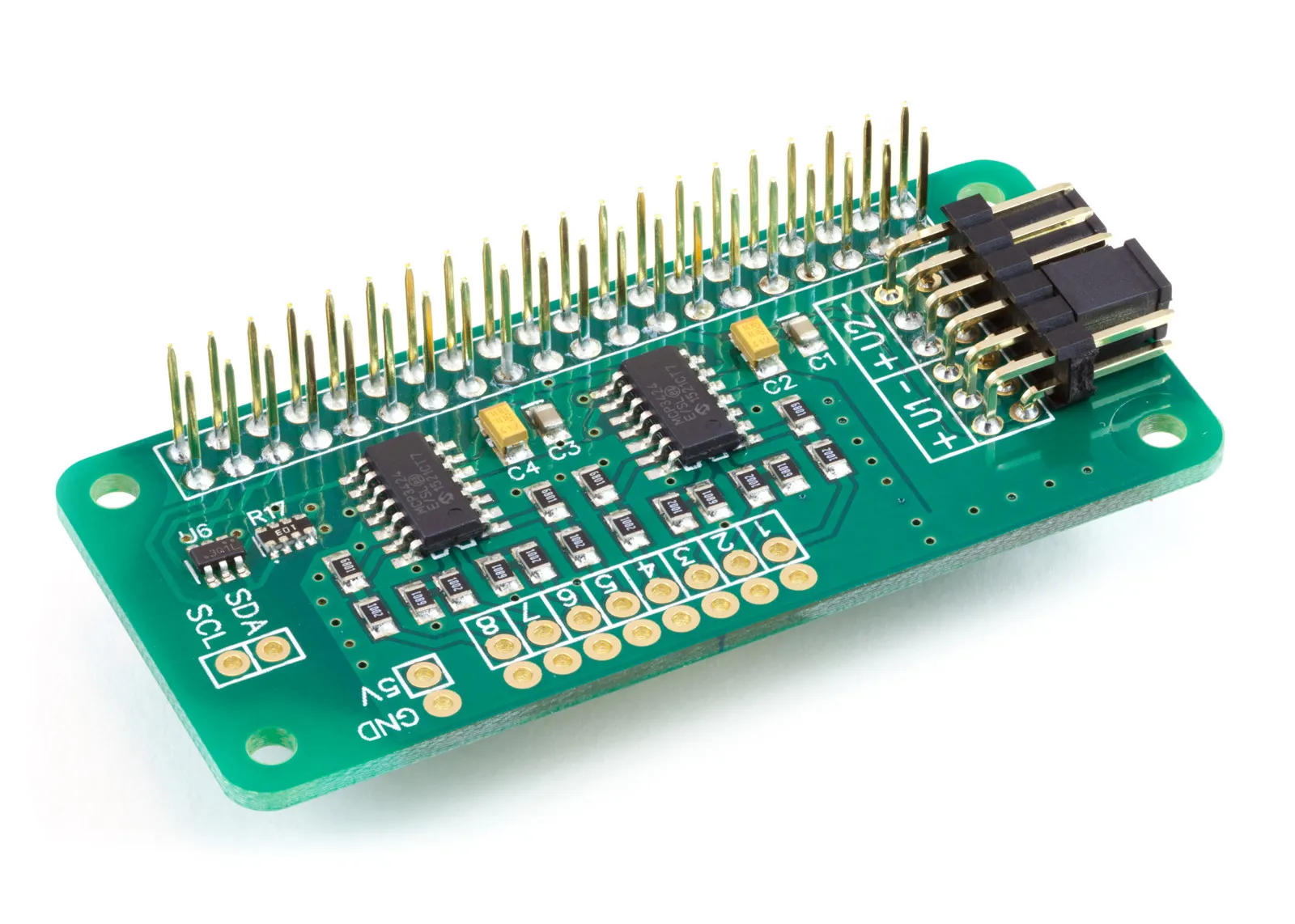
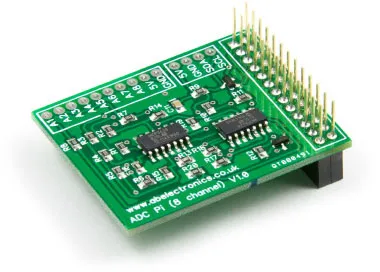
ADC Pi
8 Channel 17-bit Single-Ended Analogue to Digital Converter for the Raspberry Pi and Single-Board Computers
£17.99 ex VAT
This item has been replaced with the ADC Pi 3.0
The ADC Pi is an 8-channel 17-bit analogue to digital converter designed to work with the Raspberry Pi platform. The ADC Pi is based on two Microchip MCP3424 A/D converters, each containing 4 analogue inputs with up to 18-bit resolution. The MCP3424 is a delta-sigma A/D converter with low noise differential inputs.
Features
- 8 x 17-bit 0 to 5V Single Ended Inputs
- Control via the Raspberry Pi I2C port
- Stack up to 4 ADC Pi V2 boards on a single Raspberry Pi
- Jumper selectable I2C addresses
- Buffered 5V I2C port
- Based on the MCP3424 from Microchip Technologies Inc
- Single Ended full-scale range of 5.0V
- On-board 2.048V reference voltage (Accuracy ± 0.05%, Drift: 15 ppm/°C)
- On-Board Programmable Gain Amplifier (PGA): Gains of 1, 2, 4 or 8
- Programmable Data Rate Options:
- 3.75 SPS (17 bits)
- 15 SPS (15 bits)
- 60 SPS (13 bits)
- 240 SPS (11 bits) - One-Shot or Continuous Conversion Options
Introduction:
The ADC Pi is pin-compatible with the Raspberry Pi model B+.
We designed the ADC Pi to work as a single-ended A/D converter using the internal 2.048V reference voltage with the -V pins tied to the ground. A voltage divider on the ADC Pi board brings the input voltage range to a much more useful 0 – 5.06V. In this configuration, the sample size is 17 bits for each channel.
The ADC Pi is powered through the host Raspberry Pi using the GPIO port, and extended pins on the GPIO connector allow you to stack the ADC Pi along with other development boards.
The two MCP3424 A/D converters communicate via i2c to the host Raspberry Pi giving you eight analogue inputs. A logic level converter is included on the ADC Pi board, giving you a buffered 5V I2C port making it easy to add other I2C devices which operate at 5 volts without damaging the Raspberry Pi 3.3 volt I2C port. The I2C buffer uses N-channel MOSFETs with a maximum drain current of 100mA.
Datasheets for the MCP3424 can be found on the technical information tab.
The I2C address bits are selectable using the onboard jumpers. The MCP3424 supports up to 8 different I2C addresses, so with two A/D converters on each ADC Pi, you can stack up to 4 ADC Pi boards on a single Raspberry Pi, giving you 32 ADC inputs.
The MCP3424 contains an onboard 2.048V reference voltage with an input range of ±2.048V differentially (full-scale range of 4.096V/PGA). A programmable Gain Amplifier gives the user a selectable gain of x1, x2, x4 or x8 before the analogue to digital conversion occurs.
The data rate for analogue to digital conversions is 3.75 (17-bit), 15 (15-bit), 60 (13-bit) or 240 (11-bit) samples per second. Data rate and resolution can be configured within the software using the I2C interface.
Unused inputs should be tied to ground.
I2C Address Selection
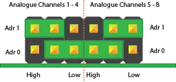
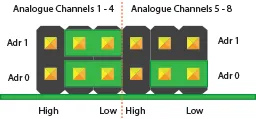
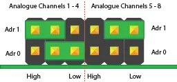
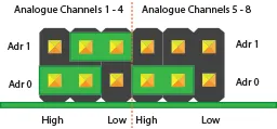
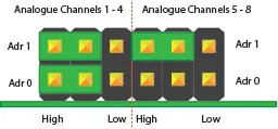
The MCP3424 analogue to digital converter contains two address select pins, which can be tied to Vss, Vdd or left floating. This gives 8 possible I2C addresses for each chip. The ADC Pi V2 contains two MCP3424 chips so that you can stack up to 4 ADC Pi V2 boards on a single Raspberry Pi. To simplify address selection on the ADC Pi V2, we have included a set of address selection pins which can be configured using the included jumpers. The illustrations below show the four recommended configurations for your ADC Pi V2 and the associated I2C addresses.
Note:
Disconnect the ADC Pi V2 from the Raspberry Pi before changing the address pins. You may need to short the 5V and ground with a resistor to discharge the capacitors for the new addresses to be recognised.
I2C Address Table
| Adr 0 | Adr 1 | I2C Address |
|---|---|---|
| Low or Float | Low or Float | 0x68 |
| Low | Float | 0x69 |
| Low | High | 0x6A |
| Float | Low | 0x6B |
| High | Low | 0x6C |
| High | Float | 0x6D |
| High | High | 0x6E |
| Float | High | 0x6F |
Warning
Do not under any circumstances connect the two centre pins together. This will create a direct short between the 5V and ground pins and damage or destroy your Raspberry Pi and ADC Pi Plus board.

Recommended Address Configurations
Configuration 1:
Analogue Channels 1-4 = I2C Address: 0x68
Analogue Channels 5-8 = I2C Address: 0x69
Configuration 2:
Analogue Channels 1-4 = I2C Address: 0x6A
Analogue Channels 5-8 = I2C Address: 0x6B
Configuration 3:
Analogue Channels 1-4 = I2C Address: 0x6C
Analogue Channels 5-8 = I2C Address: 0x6D
Configuration 4:
Analogue Channels 1-4 = I2C Address: 0x6E
Analogue Channels 5-8 = I2C Address: 0x6F
Datasheets
Input Ratings & Specifications
| Item | Rating |
|---|---|
| Vdd (5V pin on I2C bus) | 5.0V |
| All AD inputs and outputs | VSS–0.4V to VDD+0.4 V |
| Current at Input Pins | ±2 mA |
| I2C SDA/SCL voltage | 5.0 V |
| I2C port current | 100 mA |
Sample Code
Arduino, C, Windows 10 IOT and Python libraries are available for this development board. You can download all of the libraries from GitHub at:
AB Electronics UK GitHub Repository
Download the Arduino libraries from: Arduino Libraries GitHub Repository
To download the C libraries to your Raspberry Pi, type in the terminal:
git clone https://github.com/abelectronicsuk/ABElectronics_C_Libraries.git
To download the Python libraries to your Raspberry Pi, type in the terminal:
git clone https://github.com/abelectronicsuk/ABElectronics_Python_Libraries.git
Download the Windows 10 IOT libraries from:Windows 10 IOT GitHub Repository


Tutorials
We have a range of tutorials for the ADC Pi in our Knowledge Base
ADC Pi Tutorials
Note: documents in Portable Document Format (PDF) require Adobe Acrobat Reader 5.0 or higher to view, download Adobe Acrobat Reader or other PDF reading software for your computer or mobile device.
Also useful for your Raspberry Pi project
Temperature & Sensing
1 Wire Pi Plus
Connect dozens of 1-Wire sensors - temperature, iButtons, EEPROMs - via a single GPIO pin. Stacks directly on the 40-pin header.
Analogue I/O
ADC Pi
Read up to 8 analogue inputs - perfect for pairing with your temperature sensors or other analogue-output devices.
All-in-one
Expander Pi
Combines ADC, DAC, 32 GPIO ports and a real-time clock on one board. The most versatile board for complex Raspberry Pi projects.
Related Articles
- Delta-Sigma Pi (Discontinued)
- IO Pi (Discontinued)
- ADC Pi (Discontinued)
- Serial Pi (Discontinued)
- Expander Pi (Discontinued)
- Logic Level Converter (Discontinued)
- RTC Pi (Discontinued)
- ADC DAC Pi (Discontinued)
- Buffer Pi - Legacy Product
- RTC Alarm Pi (Discontinued)
- Com Pi (Discontinued)
- IO Pi Plus 1.0 (Discontinued)
- IO Pi Zero (Discontinued)
- 1 Wire Pi (Discontinued)
- 1 Wire Pi Plus 1.0 (Discontinued)
Order these Boards
ADC Pi
8 Channel 17-bit Single-Ended Analogue to Digital Converter for the Raspberry Pi and Single-Board Computers
£17.99 ex VAT