The AB Electronics UK Knowledge Base provides support solutions, tutorials and troubleshooting guides.

YOU WILL NEED THIS BOARD
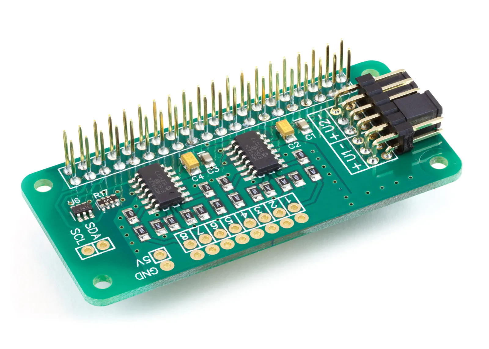
ADC Pi
8 Channel 17-bit Single-Ended Analogue to Digital Converter for the Raspberry Pi and Single-Board Computers
£17.99 ex VAT
General Questions
Q: What is the difference between the "ADC Pi" and the "ADC Differential Pi"?
A: The ADC Pi is designed for single-ended measurements (voltage relative to ground) and includes on-board voltage dividers. These dividers allow the ADC Pi to measure voltages in the 0V to 5.06V range, which is ideal for most standard sensors. The ADC Differential Pi does not have voltage dividers. It measures the voltage difference between two pins directly, with a maximum range of ±2.048V. It is intended for low-voltage signals or users who want to build their own custom input circuitry.
Q: Can I use the ADC Pi with a Raspberry Pi 5 or Zero?
A: Yes. The ADC Pi connects via the GPIO header and communicates over the I2C bus, which is standard across all Raspberry Pi models (1B, 2 3A, 3B, 4, 5, Zero, etc.).
Technical Specifications & Hardware
Q: What is the maximum voltage I can measure on the ADC Pi?
A: The maximum input voltage is approximately 5.06 Volts. The board utilises a voltage divider consisting of a 10KΩ resistor and a 6.8KΩ resistor. This scales the 5V input down to the ~2.048V limit of the MCP3424 chip. Warning: Exceeding this voltage significantly can damage the ADC chip.
Q: How do I measure higher voltages?
A: You can increase the maximum input voltage by adding a resistor in series with the input to increase the resistance of the on-board voltage divider. We have a calculator you can use to find the correct resistor value for your application. ADC Pi Input Resistor Calculator
Q: What is the input impedance of the channels?
A: The input impedance is approximately 16.8 kΩ (10kΩ + 6.8kΩ resistors in series). Note: If you are measuring a sensor with high output impedance (like a weak battery or specific analogue sensors), this relatively low impedance may load the circuit and cause voltage drops, resulting in lower-than-expected readings. For high-impedance inputs, we recommend using an operational amplifier to buffer the input or the ADC Differential Pi, which has high-impedance inputs.
Q: Can I change the Gain (PGA) setting?
A: Yes, the MCP3424 chip supports Programmable Gain Amplifier (PGA) settings of 1x, 2x, 4x, and 8x. However, because the ADC Pi has fixed voltage dividers, increasing the gain reduces your maximum measurable voltage.
- Gain 1x: Max ~5.06V
- Gain 2x: Max ~2.53V
- Gain 4x: Max ~1.26V
- Gain 8x: Max ~0.63V
Q: How fast can it sample?
A: The speed depends on the resolution (bit-depth) you select. The MCP3424 is a Delta-Sigma ADC, prioritised for precision rather than speed.
- 12-bit: ~240 samples per second (SPS)
- 14-bit: ~60 SPS
- 16-bit: ~15 SPS
- 18-bit: ~3.75 SPS
It is generally not suitable for audio recording or oscilloscope-like applications. For applications that require a higher sample rate, we sell the ADC-DAC Pi and Expander Pi development boards, which use SPI-based ADC inputs.
Setup & Troubleshooting
Q: I am getting an "OSError: [Errno 121] Remote I/O error". What is wrong?
A: This usually indicates the Raspberry Pi cannot see the ADC board.
- Check I2C: Ensure the I2C bus is enabled in raspi-config.
- Check Connections: Verify the board is seated correctly on the GPIO pins.
- Check Solder Joints: Ensure there are no solder bridges or dry joints between the pins on the GPIO connector or the address-select connector.
- Check Address Conflicts: Run i2cdetect -y 1. The ADC Pi defaults to addresses 0x68 and 0x69. Address 0x68 is also commonly used by RTC (Real Time Clock) modules. If you have an RTC, you must change the ADC Pi address using the on-board jumpers.
Q: Can I stack multiple ADC Pi boards?
A: Yes, you can stack up to 4 boards on a single Raspberry Pi. You must configure the jumpers on each board to use a unique pair of I2C addresses (e.g., Board 1: 0x68/0x69, Board 2: 0x6A/0x6B, etc.), allowing for up to 32 analogue input channels.
Q: My readings are slightly inaccurate. How do I calibrate it?
A: The resistors used in the voltage dividers have a 1% tolerance, which can lead to small variances. You can compensate for this in software by measuring a known, precise voltage source (like a multimeter reference) and adjusting a conversion factor in your code slightly to match.
Q: How do I assemble the ADC Pi?
A: This video from AB Electronics UK provides a visual guide on assembling the ADC Pi, demonstrating the soldering process for the GPIO and address-select headers, which is a critical first step for setting up the board correctly.
Watch our assembly guide on YouTube. (opens in a new window)
Also useful for your Raspberry Pi project
Temperature & Sensing
1 Wire Pi Plus
Connect dozens of 1-Wire sensors - temperature, iButtons, EEPROMs - via a single GPIO pin. Stacks directly on the 40-pin header.
Analogue I/O
ADC Pi
Read up to 8 analogue inputs - perfect for pairing with your temperature sensors or other analogue-output devices.
All-in-one
Expander Pi
Combines ADC, DAC, 32 GPIO ports and a real-time clock on one board. The most versatile board for complex Raspberry Pi projects.
Related Articles
- Getting Started with the ADC Pi
- Using the ADC Pi with Arduino
- ADC Pi Data Logger
- ADC Pi with ACS712
- ADC Pi with HIH-4000
- ADC Pi with TMP36
- Using 4-20mA sensors with the ADC Pi
- ADC Sample Rate Comparison
- ADC Pi with Raspberry Pi Pico
- ADC Pi with Capacitive Soil Sensor
- ADC Pi FAQ
- ADC Pi - Plotting Voltages in a GUI
Order these Boards
ADC Pi
8 Channel 17-bit Single-Ended Analogue to Digital Converter for the Raspberry Pi and Single-Board Computers
£17.99 ex VAT