The AB Electronics UK Knowledge Base provides support solutions, tutorials and troubleshooting guides.

In this tutorial, we will make a binary counter using 8 LEDs. You will need your Raspberry Pi, an Expander Pi, 8 red LEDs and 8 200R resistors.
We will use the AB Electronics Python library to talk to the Expander Pi. To download the library, visit our Python Library and Demos knowledge base article.
You must enable i2c on your Raspberry Pi; see our other tutorial on I2C: I2C, SMBus and Raspbian Linux.
The AB Electronics Python library uses another library called python3-smbus; you can install it using apt-get with the following commands.
sudo apt-get update
sudo apt-get install python3-smbus
With the libraries installed and the Raspberry Pi configured to use i2c, we can begin building our project.
Stage 1 – Blinking an LED
If you haven’t done so, install your Expander Pi onto the Raspberry Pi by connecting it to the GPIO header. Make sure your Raspberry Pi is turned off when you do this to minimise the risk of damaging the Raspberry Pi or the Expander Pi.
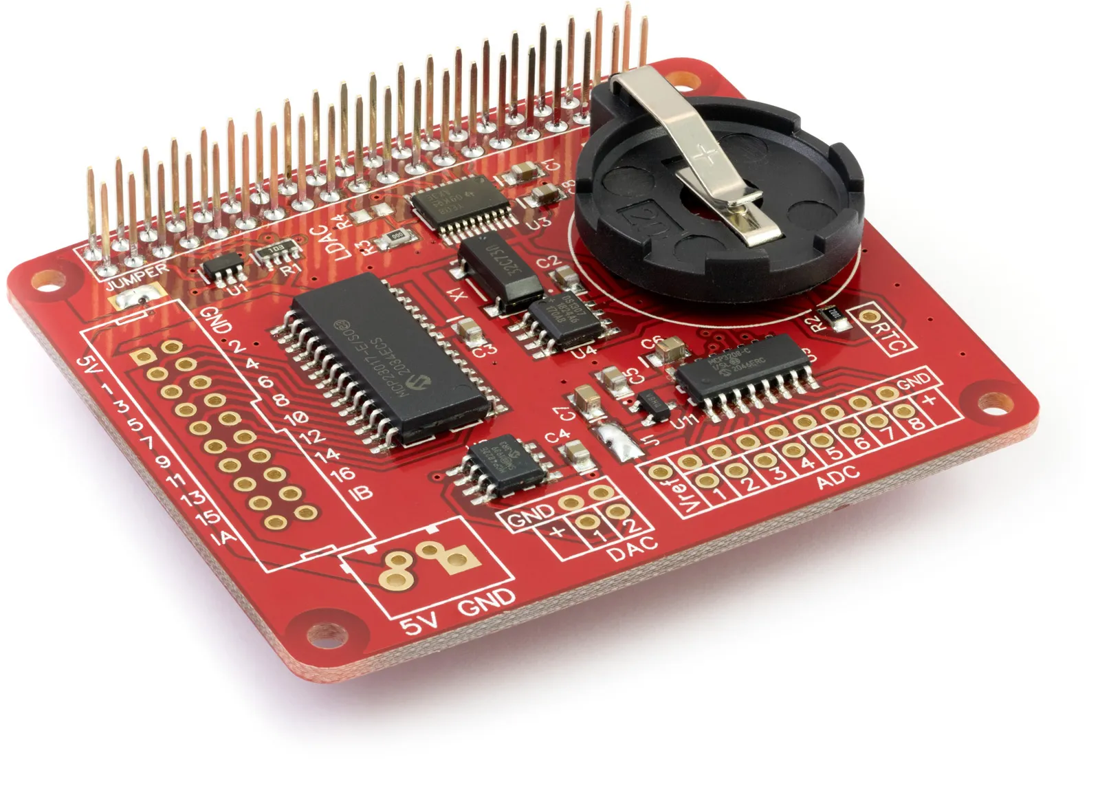
Next, connect the LED and resistor in series between Pin 1 of the IO port on the Expander Pi and the ground pin, as shown in the picture.
The Expander Pi contains an MCP23017 I/O controller chip from Microchip. The MCP23017 is an i2c-based controller having 16 I/O pins, which can be configured individually as inputs or outputs.
The maximum current you can draw from any of the pins on the MCP23017 is 25mA, so we limit the current to a safe level by using the 200R resistor in series with the LED. The maximum current you can draw from the combined pins is 125mA.
We will create a new Python program file for this tutorial called demo_iowrite.py. You can use your favourite text editor to write the program. A complete example of demo_iowrite.py is available in the ABElectronics_Python_Libraries/ABElectronics_ExpanderPi/demos folder.
At the top of your program, you will need to import the IO library and time library.
#!/usr/bin/env python
import ExpanderPi
import time
The Expander Pi library is used for all communication with your Expander Pi; it gives you control over almost everything that can be done with the MCP23017 controller.
We will create an instance of the IO class and call it io.
io = ExpanderPi.IO()
With our new instance of the IO class, we can access all available methods for controlling the Expander Pi. Let’s begin by setting the pins to be output on pins 1 to 8.
io.set_port_direction(0, 0x00)
The 16 channels on the I/O bus are split into two 8-pin ports. Port 0 controls pins 1 to 8, while port 1 controls pins 9 to 16. Having two 8-pin ports allows us to change the direction on 8 pins at once by sending an 8-bit byte of information to the Expander Pi. You can also set each pin separately using the set_pin_direction command, but for our tutorial today, we will use set_port_direction.
set_port_direction takes two variables; the first is the port you want to control, 0 for pins 1 to 8 and 1 for pins 9 to 16. The second variable is the command byte for setting the individual pin directions. Setting a pin to 0 makes it an output, while setting it to 1 makes it an input; remember, 0 = out, 1 = in.
As a byte in binary is 8 bits long, each bit represents one of the pins on the selected port. The least significant bit, or the one nearest the right, represents the lowest pin number, while the most significant bit or the one nearest the left, represents the highest pin number. If we wanted to set pins 1 to 4 as inputs and 5 to 8 as outputs, we could send the binary number 00001111. If we wished for pin 7 to be an input and everything else to be an output, we could send the binary number 01000000.
When working in Python or most other languages, it’s the standard convention when dealing with bytes to use hexadecimal rather than binary numbers, so 00001111 would become 0x0F while 01000000 becomes 0x40. If you are not very good at converting binary and hexadecimal in your head, we have an online converter you can use.
As we want all of the pins to be outputs, we will send the binary number 00000000, which converted to hexadecimal is 0x00.
Next, we will turn off all pins on port 0 with the write_port method.
io.write_port(0, 0x00)
As with set_port_direction, write_port takes two variables: the port to write to 0 or 1 and the value to send to the port. Sending a 0 turns a pin off while sending a 1 turns the pin on.
The Expander Pi is now set up for blinking our LED with all the pins on port 0 set as outputs and switched off. So, how do we make an LED blink?
We will first need a loop so that the same commands can run repeatedly. This can be done with a simple while loop.
while True:
As True is always true, the while loop will continue until you exit the program with a Ctrl-C.
We have an LED connected to pin 1, so we only need to talk to pin 1. We could use the write_port command, but that would update every pin on the port, so if we have anything else connected to the other pins, it would also affect them. We need a way to write to just one pin at a time, and we do that with the write_pin method.
io.write_pin(1, 1)
write_pin takes two variables: the first is the pin you want to talk to, 1 to 16, and the second variable controls the state of that pin. 1 will turn the pin on, and 0 will turn the pin off.
We could now use another write_pin command to turn the LED off, but the program will switch the LED on and off so fast that you will see a glowing LED. We need a short delay between turning the pin on and off; for that, we use the time.sleep method.
time.sleep(1)
time.sleep takes one variable, a number representing the number of seconds to wait. 1 will make the program sleep for 1 second while 0.1 would wait for 100ms.
Next, we add another write_pin command to turn the LED off and another sleep command to wait for another second.
     io.write_pin(1, 0)
     time.sleep(1)
That is everything we need to make an LED blink; your program should now look like this.
#!/usr/bin/env python
import ExpanderPi
import time

io = ExpanderPi.IO()

io.set_port_direction(0, 0x00)
io.write_port(0, 0x00)

while True:
    io.write_pin(1, 1)
    time.sleep(1)
    io.write_pin(1, 0)
    time.sleep(1)
Save your program and run it in a command terminal using
python3 demo_iowrite.py
If everything goes as planned, your LED should turn on and off every second.
Stage 2 – Making a binary counter
Now we have one LED that blinks; let us expand on that and make an LED counter that counts from 1 to 255 in binary.
Connect your remaining 7 LEDs and resistors to pins 2 to 8, as shown in the picture.
We will modify the previous program to make it display numbers on the LEDs. First, save your program to a new file called tutorial1a.py.
Everything until the while loop can stay as it was; we still need to set all the pins to outputs and turn them off. Remove all of the commands after while True:
We want a counter that counts from 0 to 255; the easiest way is with a for loop.
for x in range(0,255):
The for loop will loop through the numbers from 0 to 255 and store the current number in the variable x.
Next, we will write out the current number to port 0 using the write_port command.
io.write_port(1, x)
This will send the variable x to the port and display it as a binary number on the LEDs. We want to make the program sleep for half a second between each count so we can see the numbers increase.
time.sleep(0.5)
Once the for loop has finished counting to 255, it will jump onto the following command in the program. We will send a final write_port command to turn all the LEDs off before the while loop starts the counter again.
io.write_port(1, 0x00)
That is everything; your program should now look like this.
#!/usr/bin/env python
import ExpanderPi
import time

io = ExpanderPi.IO()

io.set_port_direction(0, 0x00)
io.write_port(0, 0x00)

while True:

   for x in range(0,255):
      io.write_port(1, x)
      time.sleep(0.5)

   io.write_port(1, 0x00)
Save the program and run it at the command prompt.
python3 demo_iowrite.py
You should see the LEDs change counting from 1 to 255 in binary. It will take about 2 minutes to count to 255; if you want it to go faster, change the time.sleep with a smaller number.
(images created with Fritzing)
Table of Contents